

Mechanical analysis of pavement of orthotropic steel deck
-
摘要: 分析在不同的荷载位置下, 对应不同沥青混凝土模量值的正交异性钢桥面铺装层的应力应变特性及与钢板的粘结性能。通过分析, 确定最不利加载位置和铺装层材料的各项力学指标, 如铺装层材料最大容许拉应力、最大容许拉应变以及粘结层材料的剪切强度等, 作为铺装层材料参照标准, 探索合理的铺装层方案。Abstract: The stress-strain properties of orthotropic steel deck pavement and adhesive performance between pavement and steel deck are analyzed under various modulus of asphalt concrete and load case.Based on the analysis, the worst-case load location and the mechanical indexes of pavement material are determined, including the maximum allowable tensile stress, tensile strain and shear strength of adhesive layer material, which can be served as reference standards of pavement material in order to search the suitable pavement project.
-
Key words:
- orthotropic steel deck /
- pavement /
- mechanical analysis /
- fatigue failure /
- load case
-

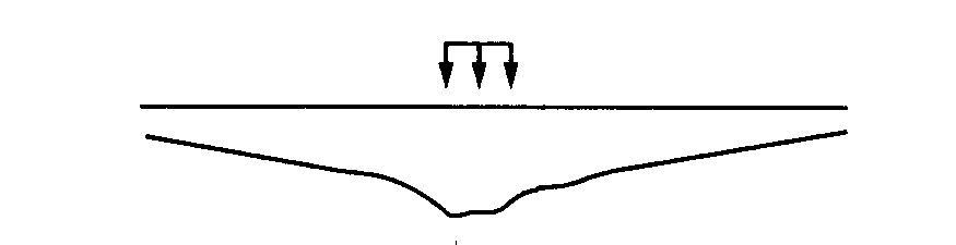
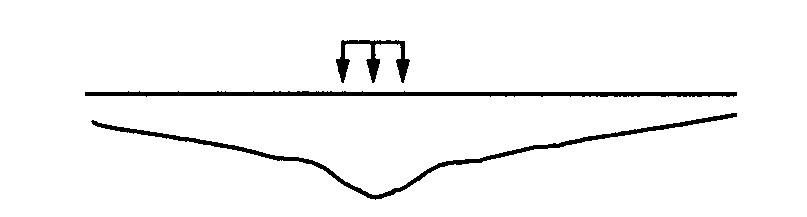
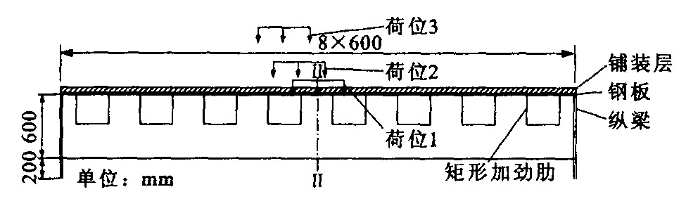
图 1 正交异性钢桥面铺装体系力学分析模型
Figure 1. Mechanical analysis model of orthotropic steel deck paving system

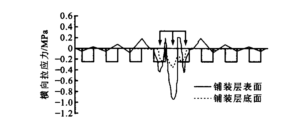
图 2 在荷位1作用下, 纵向中面铺装层表面和底面横向拉应力分布
Figure 2. Under load case 1, transversal tensile stress distribution of paving layer upper and bottom along longitudinal middle plane

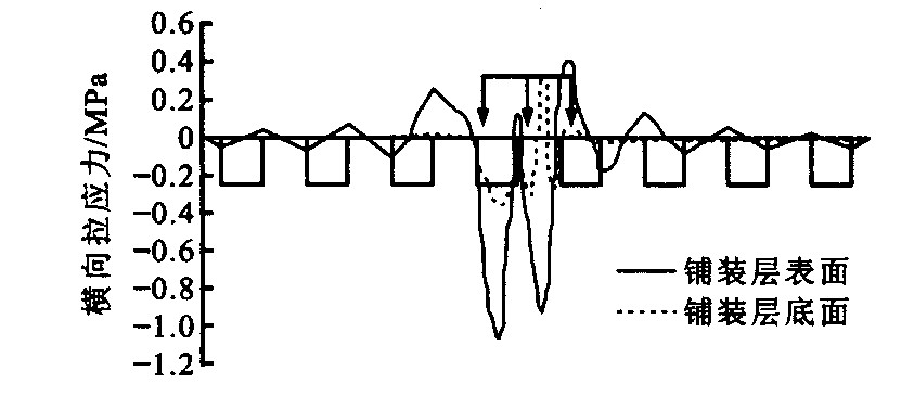
图 3 在荷位2作用下, 纵向中面铺装层表面和底面横向拉应力分布
Figure 3. Under load case 2, transversal tensile stress distribution of paving layer upper and bottom along longitudinal middle plane

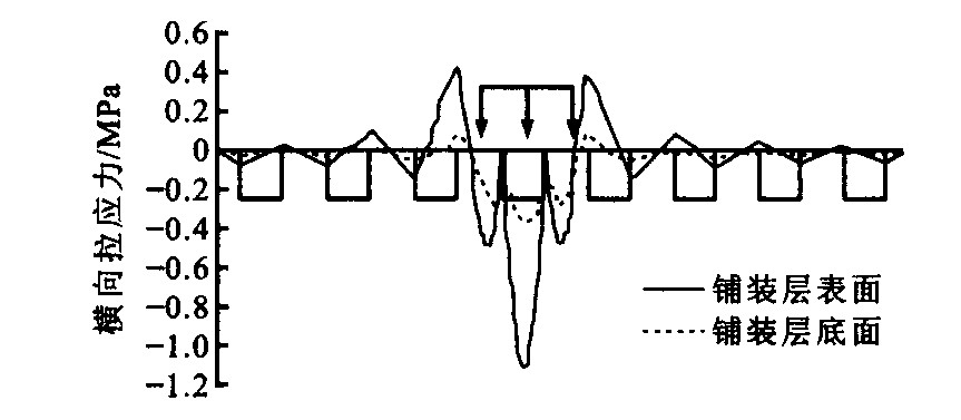
图 4 在荷位3作用下, 纵向中面铺装层表面和底面横向拉应力分布
Figure 4. Under load case 3, transversal tensile stress distribution of paving layer upper and bottom along longitudinal middle plane

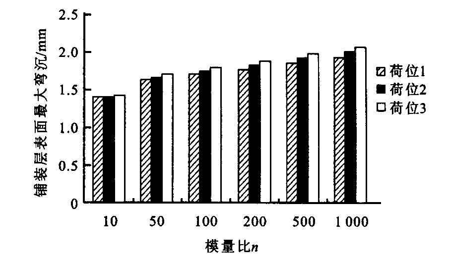
图 5 对应不同模量比n, 各荷位作用下铺装层表面最大弯沉
Figure 5. Under various load case, the maximum deflection of paving surface

图 6 在荷位1作用下, 纵向中面铺装层表面弯沉
Figure 6. Under load case 1, deflection curve of paving surface along longitudinal middle plane

图 7 在荷位2作用下, 纵向中面铺装层表面弯沉
Figure 7. Under load case 2, deflection curve of paving surface along longitudinal middle plane

图 8 在荷位3作用下, 纵向中面铺装层表面弯沉
Figure 8. Under load case 3, deflection curve of paving surface along longitudinal middle plane
表 1 本文模型计算结果与其它大桥计算结果比较
Table 1. Compare the calculation results by the model of this paper with other bridges
铺装层表面 最大位移/mm 肋相对挠度/mm 曲率半径/m 最大横向拉应力/MPa 最大横向拉应变/με 海沧大桥 纵向加劲肋处 0.842 2 0.167 3 33.60 0.130 114.5 本文结果(海沧大桥) 纵向加劲肋处 0.850 1 0.168 0 33.95 0.124 115.2  石大桥
石大桥纵向加劲肋处 0.1200 55.20 160.0 本文结果( 石大桥)纵向加劲肋处 0.1290 55.46 161.2  下载: 导出CSV
表 2 随模量比n改变, 在荷位1作用下铺装层的最大拉应力与拉应变
Table 2. Under load case 1, the maximum tensile stress and strain with the change ofn
模量比n σ1/MPa σymax/MPa σxmax/MPa εymax/10-6 εxmax/10-6 10 0.94295 0.94288 0.43012 48.78 23.22 50 0.51759 0.51755 0.13888 122.37 36.07 100 0.38442 0.37295 0.07655 154.83 38.49 200 0.26944 0.25201 0.04414 180.94 41.06 500 0.14279 0.12117 0.02548 202.61 49.36 1000 0.13702 0.05475 0.01965 211.34 64.50
下载: 导出CSV
表 3 随模量比n改变, 在荷位2作用下铺装层的最大拉应力与拉应变
Table 3. Under load case 2, the maximum tensile stress and strain with the change ofn
模量比n σ1/MPa σymax/MPa σxmax/MPa εymax/10-6 εxmax/10-6 10 1.26001 1.25984 0.41415 53.39 19.87 50 1.13671 1.12608 0.14658 254.34 34.34 100 0.92757 0.91316 0.08930 400.80 39.86 200 0.68029 0.65951 0.09156 563.85 46.28 500 0.43158 0.41603 0.06627 816.38 62.82 1000 0.32133 0.30938 0.05445 1108.40 78.67
下载: 导出CSV
表 4 随模量比n改变, 在荷位3作用下铺装层的最大拉应力与拉应变
Table 4. Under load case 3, the maximum tensile stress and strain with the change ofn
模量比n σ1/MPa σymax/MPa σxmax/MPa εymax/10-6 εxmax/10-6 10 1.53810 1.53591 0.39452 81.40 21.03 50 1.10980 1.10904 0.15568 263.57 39.18 100 0.77164 0.77105 0.10031 359.53 50.34 200 0.47678 0.47634 0.07019 437.99 59.17 500 0.21963 0.21933 0.03798 494.31 72.92 1000 0.13857 0.11294 0.02428 509.86 90.21
下载: 导出CSV
表 5 随模量比n的改变, 荷载作用下铺装层与钢板间的层间最大剪应力
Table 5. The maximum interlayer shear stress between paving layer and steel deck
模量比n 层间最大横向剪应力τymax/MPa 层间最大纵向剪应力τxmax/MPa 荷位1 荷位2 荷位3 荷位1 荷位2 荷位3 10 0.93419 1.13514 0.95316 0.55621 0.55930 0.53543 50 0.66119 0.78015 0.67760 0.40951 0.41166 0.38537 100 0.48063 0.57950 0.48812 0.31925 0.32179 0.29888 200 0.31207 0.39481 0.31319 0.23504 0.23741 0.22030 500 0.15274 0.24804 0.15122 0.15619 0.15784 0.14832 1000 0.08870 0.23129 0.11194 0.12192 0.12307 0.11751
下载: 导出CSV
-
[1] Bild S. Contribution to the improvement of the durability of asphalt pavement on orthotropic steel bridge decks[D]. Achen: RWTH Achen, 1985. [2] 方萍, 何兆益, 周虎鑫. 正交异性钢桥面板与沥青混凝土铺装的计算分析[A]. 第十三届全国桥梁学术会议论文集[C]. 北京: 人民交通出版社, 1998. [3] 钱振东, 黄卫, 茅荃. 南京长江第二大桥桥面铺装层受力分析研究[J]. 公路交通科技, 2001, 18(6): 43-46. https://www.cnki.com.cn/Article/CJFDTOTAL-GLJK200106011.htm [4] 童乐为, 沈祖炎. 正交异性钢桥面板静力试验和有限元分析[J]. 同济大学学报, 1997, 25(6): 617-621. https://www.cnki.com.cn/Article/CJFDTOTAL-TJDZ199706000.htm [5] Mabsout Me. Finite-element analysis of steel girder highway bridges[J]. ASCE J. Bridge Engineering, 1997, 2(3): 49-55. [6] Heins C P, Looney C T G. Bridge analysis using orthotropic plate theory[J]. J. Struct. Div. ASCe, 1968, 93 (ST2): 102-111. [7] 交通部重庆公路科学研究所. 特大跨径桥梁铺装层与正交异性钢桥面板的受力分析和理论研究[R]. 重庆: 交通部重庆公路科学研究所, 1999. -


 点击查看大图
计量
- 文章访问数: 600
- HTML全文浏览量: 181
- PDF下载量: 743
- 被引次数: 0
