

Review of auxiliary braking technologies of commercial automobile
-
摘要: 在商用汽车频繁制动或长时间持续制动时, 为了提高主制动器使用寿命和制动效能, 分析了辅助制动装置的结构与工作原理, 介绍了适用于柴油发动机车辆的发动机制动与排气制动技术和适用于一般商用车辆的辅助制动技术——电涡流缓速器、永久磁铁式缓速器与液力缓速器, 研究了提高制动力矩、改善散热效能、减小拖滞力矩及优化整车匹配等有关辅助制动装置关键技术, 提出了缓速器的最大制动力矩、平均制动力矩及抗热衰退系数等效能评价指标。指出了自励式缓速器、集成式缓速器和缓速器与主制动器联合控制等是商用汽车辅助制动技术的发展方向, 从政策制定和知识产权保护方面能有力推动中国辅助制动技术的发展。Abstract: In order to improve the service life and braking ability of main brake for commercial automobile during frequent or prolonged braking, engine brake, exhaust brake applied to diesel engine automobile and eddy current retarder, permanent magnet retarder, hydraulic retarder applied to general automobile were introduced based on the analysis of their structures and working principles. The key technologies on improving braking torque and heat dissipation performance, reducing hysteresis drag torque and matching optimization with whole automobile were studied. The ability evaluation indexes about rated braking torque, average braking torque, thermal decay coefficient and so on were presented. It is pointed that self-excited retarder, integrated retarder and retarder united control will become the development trend of auxiliary braking technologies for commercial automobile, and policy formulation and the protection of intellectual property rights will effectively promoted the development of Chinese auxiliary braking technologies. 10 figs, 17 refs.
-
Key words:
- automobile engineering /
- commercial automobile /
- auxiliary braking /
- active safety /
- retarder /
- review
-

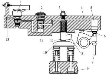
图 1 发动机制动装置
Figure 1. Engine brake device
1-Solenoid valve; 2-Low-pressure oil; 3-Adjusting screw; 4-High-pressure oil; 5-Active piston; 6-Rocker arm adjusting screw; 7-Strut; 8-Exhaust rocker arm; 9-Exhaust valve; 10-T-shaped platen of exhaust; 11-Driven piston; 12-Spherical check valve; 13-Engine oil port

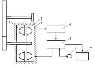
图 3 电磁气压控制的排气制动装置
Figure 3. Exhaust brake device with electromagnetic air pressure control
1-Inlet silencing valve; 2-Pneumatic cylinder; 3-Exhaust brake; 4-Pneumatic cylinder; 5-Storage pot; 6-Battery; 7-Exhaust brake switch; 8-Signal lights; 9-Clutch pedal; 10-Clutch switch; 11-Accelerate switch; 12-Fuel control arm; 13-Flameout manipulation arm; 14-Pneumatic cylinder; 15-Solenoid valve

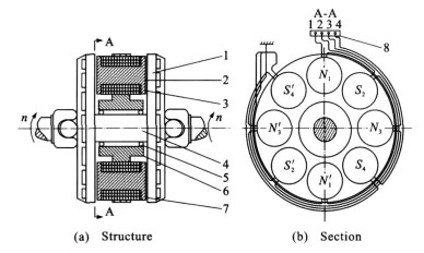
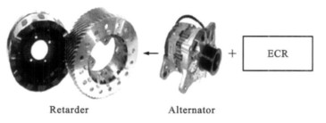
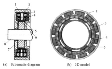
图 4 盘式电涡流缓速器结构
Figure 4. Disc-type ECR structure
1-Rotor disk; 2-Core; 3-Excitation coil; 4-Rotor axis; 5-Bearings; 6-Fixation; 7-Airgap; 8-Terminal

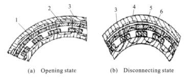
图 7 永磁式缓速器开通与断开状态时的磁路
Figure 7. Opening and disconnecting states of magnetic circuit of PMR
1-Ferromagnetic material; 2-Non-magnetic material; 3-Rotary drum; 4-Leakage magnetic line; 5-Permanent magnet; 6-Magnetic line

图 8 液力缓速器工作原理
Figure 8. Working principle of hydraulic retarder
1-Stator; 2-Rotor; 3-Shell; 4-Radiator; 5-Control valves system; 6-Pump; 7-Tank
-
[1] HU Qing-xun, HE Ren. Automotive safety technology of auxiliary brake[J]. Automobile and Accessories, 2005, 25(13): 28-29. (in Chinese) [2] LI Wen-hui, GAO Quan-jun, WEI Hong, et al. Engine auxiliary braking and its influence on the braking performance of vehicles[J]. Chinese Internal Combustion Engine Engineering, 2002, 23(4): 25-29. (in Chinese) [3] YU Qiang, CHEN Yin-san, MA Jian. Function analysis on exhaust brake of bus[J]. Journal of Xi'an Highway University, 2000, 20(S0): 5-7. (in Chinese) [4] HE Jian-qing, HE Ren, YI Feng-yan. The eddy current retarder working principle of automobile and its results[J]. Light Vehicle Technology, 2002, 30(11): 17-24. (in Chinese) [5] HE Ren, HE Jian-qing. Analysis on braking ability of automobile equipped with eddy current retarder[J]. Journal of Jiangsu University: Natural Science Edition, 2004, 25(1): 29-32. (in Chinese) [6] ZHU Ning, WANG Yong-hua. Light permanent magnet motor vehicle retarder[J]. Bus Technology and Research, 2002, 24(4): 19-20. (in Chinese) [7] HE Ren, ZHAO Wan-zhong, NIU Run-xin. Braking torque computation method of permanent magnet retarder[J]. Journal of Traffic and Transportation Engineering, 2006, 6(4): 62-65. (in Chinese) [8] SAKAMOTO H, ARAKI K, ISHIDA A, et al. Design of permanent magnet type compact RCB retarder[J]. SAE Paper 973228: 508-518. [9] SHI Jun. Vehicle hydraulic brake deceleration research[D]. Wuhan: Huazhong University of Science and Technology, 2002. (in Chinese) [10] NIU Run-xin, HE Ren. Robust design technique for permanent magnet type retarder[J]. Journal of Jiangsu University: Natural Science Edition, 2006, 27(6): 493-496. (in Chinese) [11] UM Y, TORⅡ S, EBIBARA D, et al. Characteristic of eddy current on the secondary of eddy current brake[J]. IEEE Transactions on Magnetics, 1996, 12(3): 451-457. [12] LIU Cheng-ye, HE Ren. Effect on rotor's structure parameters of eddy current retarder based on CFD[J]. Journal of System Simulation, 2008, 20(21): 5993-5998. (in Chinese) [13] ZHAO Ying-sheng, HE Ren, WANG Yong-tao, et al. Adjusting vehicle's braking stability using eddy current retarder[J]. Journal of Jiangsu University: Natural Science Edition, 2007, 28(4): 309-311. (in Chinese) [14] HE Ren, YI Feng-yan. Evaluation method of performance characteristic of eddy current retarder[J]. China Journal of Highway and Transport, 2006, 19(5): 114-118. (in Chinese) [15] MA Jian, CHEN Yin-san, YU Qiang, et al. Evaluation of retarder to automobile braking stability[J]. Journal of Traffic and Transportation Engineering, 2002, 2(1): 105-109. (in Chinese) [16] YU Qiang, CHEN Yin-san, MA Jian, et al. Braking ability of engine brake and retarder brake when bus downhill[J]. Journal of Chang'an University: Natural Science Edition, 2004, 24(2): 87-90. (in Chinese) [17] BURAIS N, FOGGIA A, NICOLAS A, et al. Numerical solution of eddy currents problems including moving conducting parts[J]. IEEE Transactions on Magnetics, 1984, 20(5): -

 下载:
下载:


 点击查看大图
计量
- 文章访问数: 493
- HTML全文浏览量: 108
- PDF下载量: 336
- 被引次数: 0
