

Back analysis of build-up effect of earth pressure behind integral abutment
-
摘要: 为了确定整体式桥台后土体在水平方向往复位移作用下的最终土压力,针对5组整体式桥台模型试验进行了有限差分数值模拟反分析;采用能够反映土体在小应变区间上高模量和高度非线性刚度特性的土体本构模型,考虑土体与桥台之间的界面特性,通过在桥台顶部施加水平位移,反分析模型试验中经过不同循环次数的台后土压力测量结果,获得了相应的土体小应变刚度参数,揭示每组试验中桥台后土体小应变刚度在往复加载过程中的演化规律;在此基础上,针对铰支座和扩展基础这2种不同的桥台底部约束条件,分别提出了估算整体式桥台后土体小应变刚度增大倍数的公式,进而提出了考虑桥台与土相互作用的整体式桥台后最终土压力的设计计算方法。研究结果表明:当桥台底部为铰支座时,往复加载前后土体小应变刚度增大倍数随桥台顶部相对位移的增大而增大,随桥台后砂土相对密度的增大而减少;当桥台底部为扩展基础时,土体小应变刚度增大倍数虽然也随桥台顶部相对位移的增大而增大,但增幅明显小于桥台底部为铰支座的工况,并且受桥台后砂土相对密度的影响不大;相比英国设计指南PD 6694-1,提出的公式能够考虑上述多个因素的影响,并能较好地预测出不同模型试验反分析得到的土体小应变刚度增大倍数,可为整体式桥台设计提供依据。Abstract: To determine the ultimate earth pressure behind integral abutment subjected to horizontal cyclic displacements, the back analysis using the finite difference numerical simulation was performed on five sets of model tests of integral abutments. A soil constitutive model capable of reflecting the high modulus and highly non-linear stiffness property of soil within the small strain range was utilized, and the properties of the interface between the soil and the abutment were considered. Through the application of horizontal displacements at the abutment top. Earth pressures behind the abutments measured at different cycles were back-analyzed. The corresponding small strain stiffness parameter of soil was obtained, and the evolution laws of the small strain stiffness of soil behind the abutments in each set of model tests during the cyclic loading process were revealed. On the basis of the above findings, the formulas were proposed to estimate the increasing multiple of the small strain stiffness of soil behind the integral abutments with a hinged base and a spread base separately. Then, a method was proposed to design and calculate the ultimate earth pressure behind the integral abutments with the consideration of soil-abutment interaction. Research results show that for the abutment with a hinged base, the increasing multiple of the small strain stiffness of soil increases with the rise in the relative displacement at the abutment top before and after the cyclic loading, while it decreases with the increase in the relative density of soil behind the abutment. For the abutment with a spread base, the increasing multiple of the small strain stiffness of soil increases at a slower rate with the rise in the relative displacement at the abutment top compared with that in the case of a hinged base, but it is slightly influenced by the relative density of soil behind the abutment. Compared with the British design guidance PD 6694-1, the proposed formulas consider the influences of the above multi-factors and can make reasonable prediction on the increasing multiple of the small strain stiffness of soil obtained from the back analysis on different model tests. It can be a reference for the design of integral abutments.
-
Key words:
- bridge engineering /
- integral abutment /
- earth pressure /
- back analysis /
- small strain stiffness /
- numerical simulation
-

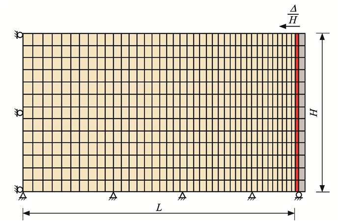
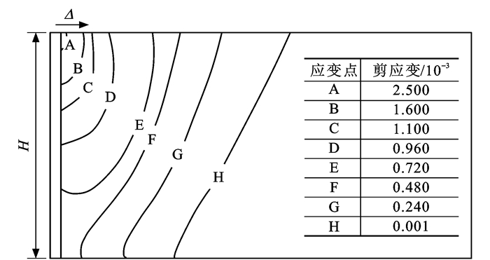
图 1 在桥台顶部施加水平位移时土体剪应变分布(Δ=10-3H)
Figure 1. Shear strain distribution of soil when horizontal displacement is applied at abutment top (Δ=10-3H)

图 2 切线剪切刚度随轴向应变的变化曲线
Figure 2. Variation curve of tangent shear stiffness with axial strain

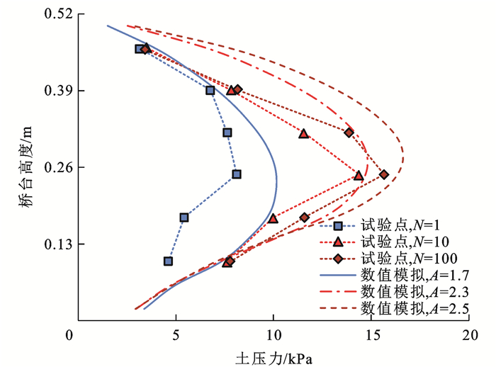
图 4 Δ/H为1.25×10-3时数值模拟与试验得到的土压力和桥台高度之间的关系(第1组模拟)
Figure 4. Relationships between earth pressure and abutment height obtained by numerical simulation and experiment when Δ/H is 1.25×10⁻³ (simulation group 1)

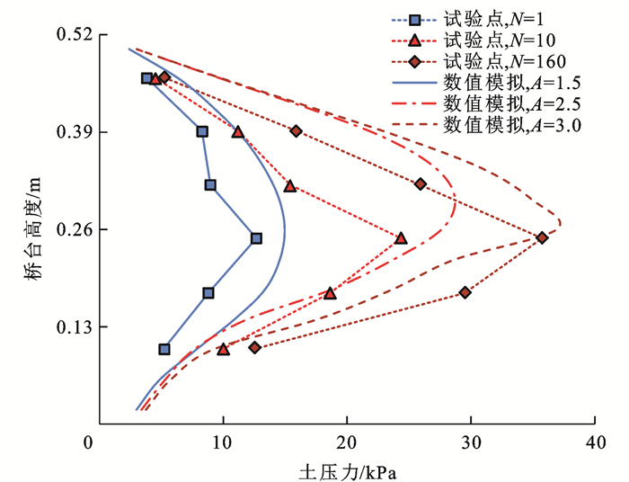
图 5 Δ/H为2.50×10-3时数值模拟与试验得到土压力和桥台高度之间的关系(第1组模拟)
Figure 5. Relationships between earth pressure and abutment height obtained by numerical simulation and experiment when Δ/H is 2.50×10⁻³ (simulation group 1)

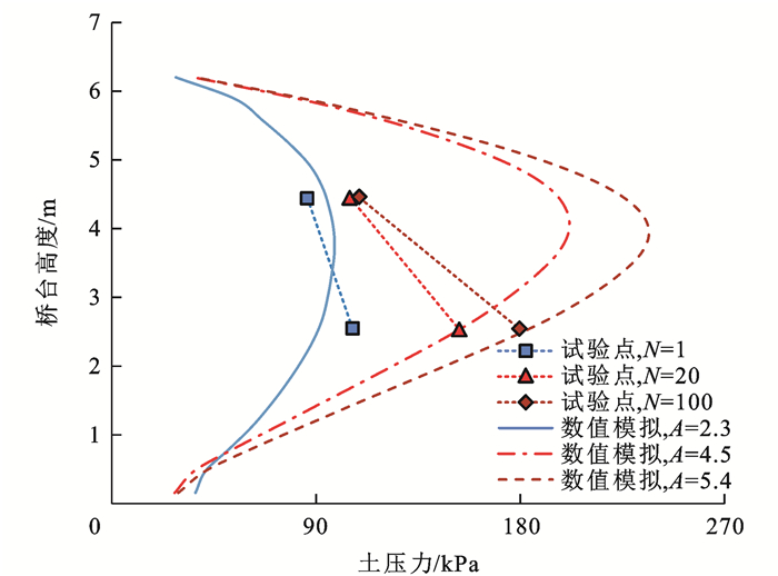
图 6 Δ/H为3.50×10-2时数值模拟与试验得到的土压力和桥台高度之间的关系(第1组模拟)
Figure 6. Relationships between earth pressure and abutment height obtained by numerical simulation and experiment when Δ/H is 3.50×10⁻² (simulation group 1)

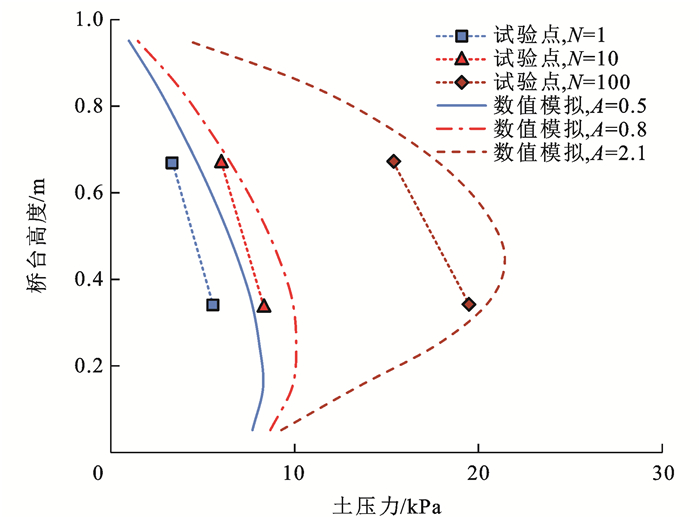
图 8 Δ/H为2.00×10-3时数值模拟与试验得到的土压力和桥台高度之间的关系(第2组模拟)
Figure 8. Relationships between earth pressure and abutment height obtained by numerical simulation and experiment when Δ/H is 2.00×10⁻³ (simulation group 2)

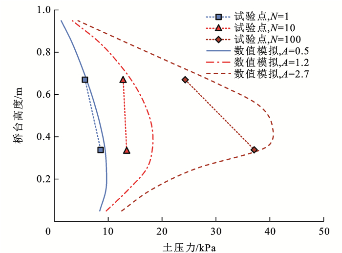
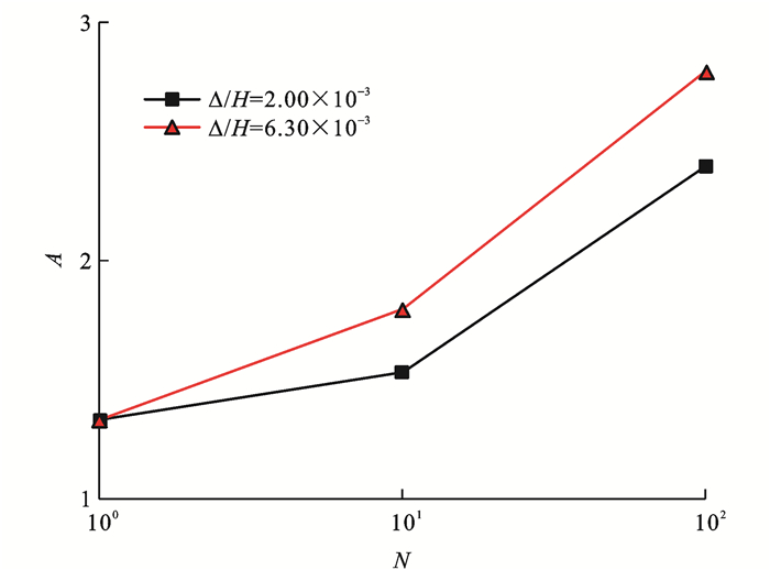
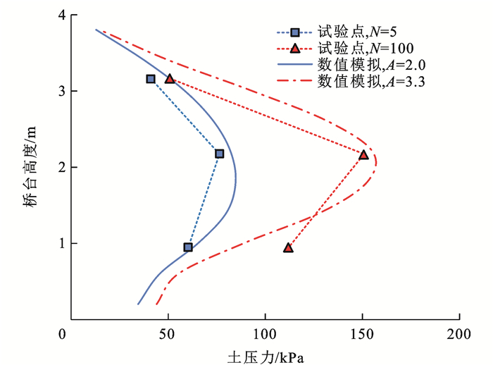
图 9 Δ/H为6.30×10-3时数值模拟与试验得到的土压力和桥台高度之间的关系(第2组模拟)
Figure 9. Relationships between earth pressure and abutment height obtained by numerical simulation and experiment when Δ/H is 6.30×10⁻³ (simulation group 2)

图 11 Δ/H为5.00×10-4时数值模拟与试验得到的土压力和桥台高度之间的关系(第3组模拟)
Figure 11. Relationships between earth pressure and abutment height obtained by numerical simulation and experiment when Δ/H is 5.00×10⁻⁴ (simulation group 3)

图 12 Δ/H为2.00×10-3时数值模拟与试验得到土压力和桥台高度之间的关系(第3组模拟)
Figure 12. Relationships between earth pressure and abutment height obtained by numerical simulation and experiment when Δ/H is 2.00×10⁻³ (simulation group 3)

图 13 Δ/H为6.30×10-3时数值模拟与试验得到的土压力和桥台高度之间的关系(第3组模拟)
Figure 13. Relationships between earth pressure and abutment height obtained by numerical simulation and experiment when Δ/H is 6.30×10⁻³ (simulation group 3)

图 16 Δ/H为5.00×10-3时数值模拟与试验得到土压力和桥台高度之间的关系(第4组模拟,松砂)
Figure 16. Relationships between earth pressure and abutment height obtained by numerical simulation and experiment when Δ/H is 5.00×10⁻³ (simulation group 4, loose sand)

图 17 Δ/H为1.00×10-2时数值模拟与试验得到的土压力和桥台高度之间的关系(第4组模拟,松砂)
Figure 17. Relationships between earth pressure and abutment height obtained by numerical simulation and experiment when Δ/H is 1.00×10⁻² (simulation group 4, loose sand)

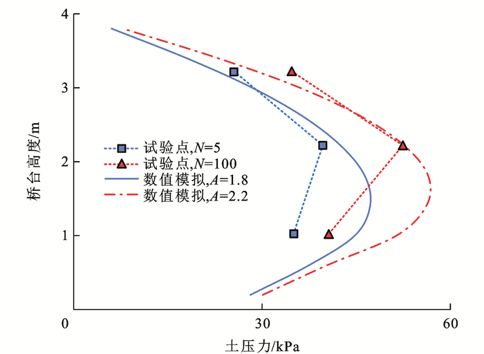
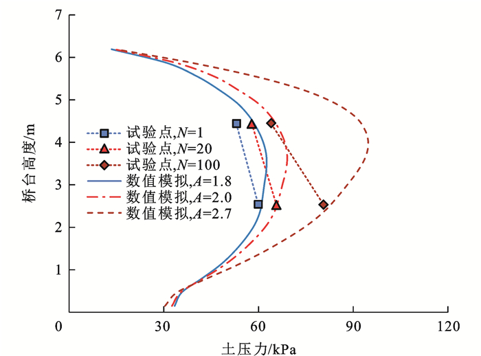
图 18 Δ/H为5.00×10-3时数值模拟与试验得到土压力和桥台高度之间的关系(第5组模拟,密砂)
Figure 18. Relationships between earth pressure and abutment height obtained by numerical simulation and experiment when Δ/H is 5.00×10⁻³ (simulation group 5, dense sand)

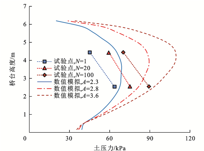
图 19 Δ/H为1.00×10-2时数值模拟与试验得到土压力和桥台高度之间的关系(第5组模拟,密砂)
Figure 19. Relationships between earth pressure and abutment height obtained by numerical simulation and experiment when Δ/H is 1.00×10⁻² (simulation group 5, dense sand)

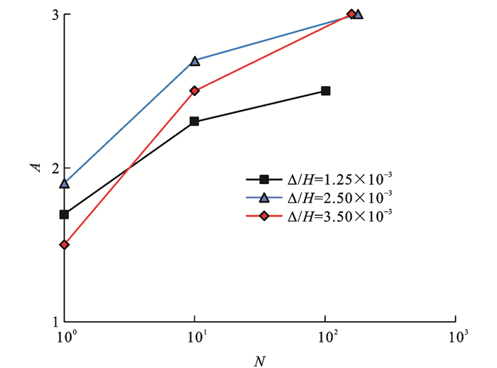
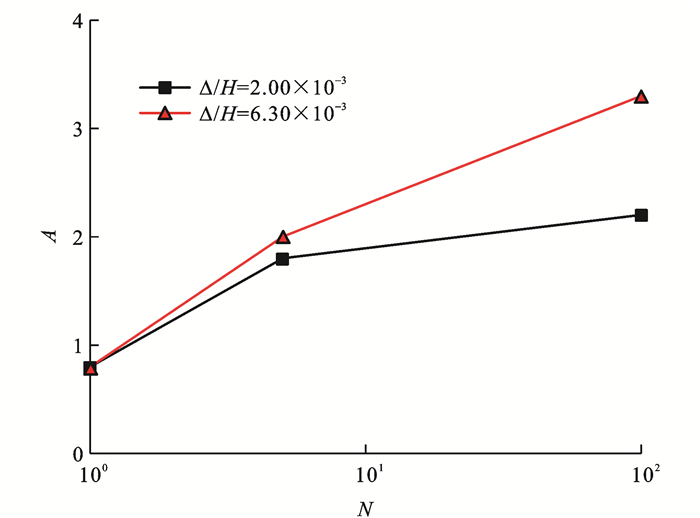
图 20 第4组模拟中A和N的关系(松砂)
Figure 20. Relationships between A and N in simulation group 4 (loose sand)

图 21 第5组模拟中A和N的关系(密砂)
Figure 21. Relationships between A and N in simulation group 5 (dense sand)

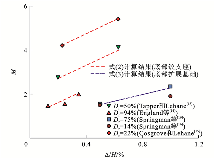
图 22 不同试验中土体刚度增大倍数与桥台顶部相对位移关系
Figure 22. Relationships between increasing multiples of soil stiffness and relative displacement at abutment top in different experiments
表 1 第1组模拟砂土参数取值
Table 1. Values of soil parameters of simulation group 1
参数 摩擦角/(°) 剪切模量/MPa A n εq(min) εq(max) 泊松比v 取值 43 按式(1)取值 反分析确定 -0.72 1.0×10⁻⁵ 5.0×10⁻² 0.3  下载: 导出CSV
表 2 第2组模拟砂土参数取值
Table 2. Values of soil parameters of simulation group 2
参数 摩擦角/(°) 剪切模量/MPa A n εq(min) εq(max) 泊松比v 取值 33 按式(1)取值 反分析确定 -0.66 1.0×10⁻⁵ 5.0×10⁻² 0.3
下载: 导出CSV
表 3 第3组模拟砂土参数取值
Table 3. Values of soil parameters of simulation group 3
参数 摩擦角/(°) 剪切模量/MPa A n εq(min) εq(max) 泊松比v 取值 33 按式(1)取值 反分析确定 -0.65 1.0×10⁻⁵ 5.0×10⁻² 0.3
下载: 导出CSV
表 4 第4组模拟砂土参数取值(松砂)
Table 4. Values of soil parameters of simulation group 4 (loose sand)
参数 摩擦角/(°) 剪切模量/MPa A n εq(min) εq(max) 泊松比v 取值 32 按式(1)取值 反分析确定 -0.61 1.0×10⁻⁵ 5.0×10⁻² 0.3
下载: 导出CSV
表 5 第5组模拟砂土参数取值(密砂)
Table 5. Values of soil parameters of simulation group 4 (dense sand)
参数 摩擦角/(°) 剪切模量/MPa A n εq(min) εq(max) 泊松比v 取值 40 按式(1)取值 反分析确定 -0.58 1.0×10⁻⁵ 5.0×10⁻² 0.3
下载: 导出CSV
表 6 不同模型试验的反分析结果
Table 6. Back analysis results for different model tests
模型试验 相对密度/% 桥台顶部相对位移/10-3 刚度参数 土体刚度增大倍数 N=1 N=100 England等[14] 94 1.25 1.7 2.5 1.47 2.50 1.9 3.0* 1.58 3.50 1.5 3.0** 2.00 Cosgrove等[15] 22 2.30 0.5 2.1 4.20 6.30 0.5 2.7 5.40 Tapper等[18] 50 2.00 0.8 2.2 2.75 6.30 0.8 3.3 4.12 Springman等[16](松砂) 14 5.00 1.8 2.7 1.50 10.00 1.8 3.4 1.90 Springman等[16](密砂) 75 5.00 2.3 3.6 1.56 10.00 2.3 5.4 2.35
下载: 导出CSV
-
[1] BANKS J R, BLOODWORTH A G. Lateral stress profiles on integral bridge abutments[J]. Proceedings of the Institution of Civil Engineers-Bridge Engineering, 2018, 171(3): 155-168. doi: 10.1680/jbren.17.00017 [2] 朱伟庆, 衡江峰, 刘永健, 等. 采用墙式整体桥台的无缝桥受力特征[J]. 交通运输工程学报, 2017, 17(6): 36-45. https://www.cnki.com.cn/Article/CJFDTOTAL-JYGC201706008.htmZHU Wei-qing, HENG Jiang-feng, LIU Yong-jian, et al. Mechanical characteristics of jointless bridge with wall-type integral abutment[J]. Journal of Traffic and Transportation Engineering, 2017, 17(6): 36-45. (in Chinese) https://www.cnki.com.cn/Article/CJFDTOTAL-JYGC201706008.htm [3] BLOODWORTH A, XU Ming, BANKS J R, et al. Predicting the earth pressure on integral bridge abutments[J]. Journal of Bridge Engineering, 2012, 17(2): 371-381. doi: 10.1061/(ASCE)BE.1943-5592.0000263 [4] TATSUOKA F, HIRAKAWA D, NOJIRI M, et al. A new type of integral bridge comprising geosynthetic-reinforced soil walls[J]. Geosynthetics International, 2009, 16(4): 301-326. doi: 10.1680/gein.2009.16.4.301 [5] XU Ming, BLOODWORTH A, CLAYTON C. Behavior of a stiff clay behind embedded integral abutments[J]. Journal of Geotechnical and Geoenvironmental Engineering, 2007, 133(6): 721-730. doi: 10.1061/(ASCE)1090-0241(2007)133:6(721) [6] 陈宝春, 王晨辉, 薛俊青, 等. 我国无伸缩缝桥梁调查与分析[J]. 建筑科学与工程学报, 2022, 39(5): 13-21.CHEN Bao-chun, WANG Chen-hui, XUE Jun-qing, et al. Investigation and analysis on the application of jointless bridges in China[J]. Journal of Architecture and Civil Engineering, 2022, 39(5): 13-21. (in Chinese). [7] OOI P S, LIN Xiao-bin, HAMADA H S, et al. Field behavior of an integral abutment bridge supported on drilled shafts[J]. Journal of Bridge Engineering, 2010, 15(1): 4-18. doi: 10.1061/(ASCE)BE.1943-5592.0000036 [8] DEJONG J T, HOWEY D S, CIVJAN S A, et al. Influence of daily and annual thermal variations on integral abutment bridge performance[M]//YEGIAN M K, KAVAZANJIAN E. Geotechnical Engineering for Transportation Projects. Reston: ASCE, 2004: 496-505. [9] KIM W, LAMAN J. Seven-year field monitoring of four integral abutment bridges[J]. Journal of Performance of Constructed Facilities, 2012, 26(1): 54-64. doi: 10.1061/(ASCE)CF.1943-5509.0000250 [10] BARKER K J, CARDER D R. The long term monitoring of stresses behind three integral bridge abutments[R]. Berkshire: Transport Research Laboratory, 2006. [11] HOPPE E, GÓMEZ J. Field study of an integral backwall bridge[R]. Charlottesville: Virginia Transportation Research Council, 1996. [12] HUNTLEYSHELLEY S A, VALSANGKARARUN A J. Field monitoring of earth pressures on integral bridge abutments[J]. Canadian Geotechnical Journal, 2013, 50(8): 841-857. doi: 10.1139/cgj-2012-0440 [13] DARLEY P, CARDER D R, BARKER K J. Seasonal thermal effects over three years on the shallow abutment of an integral bridge in Glasgow[R]. Berkshire: Transport Research Laboratory, 2000. [14] ENGLAND G L, TSANG N C M, BUSH D I. Integral bridges: a fundamental approach to the time-temperature loading problem[R]. London: Thomas Telford, 2000. [15] COSGROVE E F, LEHANE B M. Cyclic loading of loose backfill placed adjacent to integral bridge abutments[J]. International Journal of Physical Modelling in Geotechnics, 2003, 3(3): 9-16. doi: 10.1680/ijpmg.2003.030302 [16] SPRINGMAN S M, NORRISH A R M, NG C W W. Cyclic loading of sand behind integral bridge abutments[R]. Berkshire: Transport Research Laboratory, 1996. [17] NG C W W, SPRINGMAN S M, NORRISH A R M. Centrifuge modeling of spread-base integral bridge abutments[J]. Journal of Geotechnical and Geoenvironmental Engineering, 1998, 124(5): 376-388. doi: 10.1061/(ASCE)1090-0241(1998)124:5(376) [18] TAPPER L, LEHANE B. Lateral stress development on integral bridge abutments[C]//DEEKS A J, HAO H. Proceedings of Eighteenth Australasian Conference on Mechanics of Structures and Materials. Boca Raton: CRC Press, 2004: 1069-1076. [19] LEHANE B M. Lateral soil stiffness adjacent to deep integral bridge abutments[J]. Géotechnique, 2011, 61(7): 593-603. doi: 10.1680/geot.9.P.135 [20] XU Ming, CLAYTON C R, BLOODWORTH A G, et al. The earth pressure behind full-height frame integral abutments supporting granular fill[J]. Canadian Geotechnical Journal, 2007, 44(3): 284-298. doi: 10.1139/t06-122 [21] XU Ming, GUO Jin-wu. DEM study on the development of the earth pressure of granular materials subjected to lateral cyclic loading[J]. Computers and Geotechnics, 2021, 130: 103915. doi: 10.1016/j.compgeo.2020.103915 [22] 徐明, 刘鹏飞. 整体式桥台研究综述[J]. 工程力学, 2016, 33(4): 1-8. https://www.cnki.com.cn/Article/CJFDTOTAL-GCLX201604003.htmXU Ming, LIU Peng-fei. Research on integral bridge abutments[J]. Engineering Mechanics, 2016, 33(4): 1-8. (in Chinese) https://www.cnki.com.cn/Article/CJFDTOTAL-GCLX201604003.htm [23] ATKINSON J H. Non-linear soil stiffness in routine design[J]. Géotechnique, 2000, 50(5): 487-508. doi: 10.1680/geot.2000.50.5.487 [24] SIMPSON B. Retaining structures: displacement and design[J]. Géotechnique, 1992, 42(4): 541-576. doi: 10.1680/geot.1992.42.4.541 [25] JARDINE R J. Some observations on the kinematic nature of soil stiffness[J]. Soils and Foundations, 1992, 32(2): 111-124. doi: 10.3208/sandf1972.32.2_111 [26] PUZRIN A M, BURLAND J B. Non-linear model of small-strain behaviour of soils[J]. Géotechnique, 1998, 48(2): 217-233. doi: 10.1680/geot.1998.48.2.217 [27] XU Ming, SHEN Da-wei, RAKITIN B. The longitudinal response of buried large-diameter reinforced concrete pipeline with gasketed bell-and-spigot joints subjected to traffic loading[J]. Tunnelling and Underground Space Technology, 2017, 64: 117-132. doi: 10.1016/j.tust.2016.12.020 [28] DASARI G R. Modelling the variation of soil stiffness during sequential construction[D]. Cambridge: University of Cambridge, 1996. [29] 邹文浩, 徐明. 隧道开挖对地面房屋影响的三维数值分析与评估[J]. 岩土工程学报, 2015, 37(增2): 202-209. https://www.cnki.com.cn/Article/CJFDTOTAL-YTGC2015S2040.htmZOU Wen-hao, XU Ming. 3D numerical analysis and evaluation of the influence of tunneling on frame buildings[J]. Chinese Journal of Geotechnical Engineering, 2015, 37(S2): 202-209. (in Chinese) https://www.cnki.com.cn/Article/CJFDTOTAL-YTGC2015S2040.htm [30] OZTOPRAK S, BOLTON M D. Stiffness of sands through a laboratory test database[J]. Géotechnique, 2013, 63(1): 54-70. -


 点击查看大图
计量
- 文章访问数: 670
- HTML全文浏览量: 178
- PDF下载量: 50
- 被引次数: 0
