| Citation: | LUO Ren, WU Ping-bo, LIU Bin-bin. Constant air gap control simulation of linear induction motor of metro vehicle[J]. Journal of Traffic and Transportation Engineering, 2010, 10(4): 50-57. doi: 10.19818/j.cnki.1671-1637.2010.04.009

|
Compared with concrete beam bridges, steel-concrete composite bridges have the characteristics of lightweight, high strength, energy saving, environmental protection, earthquake resistance, and excellent life cycle. As a type of steel-concrete composite bridge, steel-concrete composite truss bridge is based on the optimized structural form of the concrete box girder web and bottom plate. After the concrete box girder web and bottom plate are replaced by a truss system, the advantage of clear stress on the truss system increases the utilization rate of structural materials and greatly reduces the self weight of the structure. Therefore, this type of bridge is increasingly favored and concerned by engineers and scholars.

The aspect ratio is an important parameter in the overall design of bridges, which directly affects the stress state and steel consumption of the structure. From the perspective of stress, the edge to mid span ratio should be taken as 0.6~0.8. At this point, the bending moment at the edge to mid span and the bending moment at the mid span are relatively close, and the structural bending moment distribution is uniform. From the perspective of standard assembly, the side span and mid span should be taken as the same span. In this case, the bending moment in the mid span of the side span is greater than that in the mid span, resulting in a significantly higher steel consumption for the side span chord than for the mid span chord. From the perspective of bridge aesthetics, after equal span arrangement, the bridge line appears simple, clear, and rhythmic.
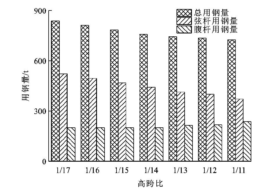
The height to span ratio is another important design parameter for bridge design, which is closely related to the steel consumption of composite truss bridges,Figure 5The relationship between the amount of steel used and the height to span ratio for a 4 × 70m standard span composite truss bridge (bridge width 12.75m).

 |
 DownLoad:
CSV
DownLoad:
CSV
The connection structure of rectangular steel-concrete composite truss bridge is mainly divided into two parts: the connection structure between the main truss segment units and the connection structure between the bridge deck assembly units and the main truss segment units.
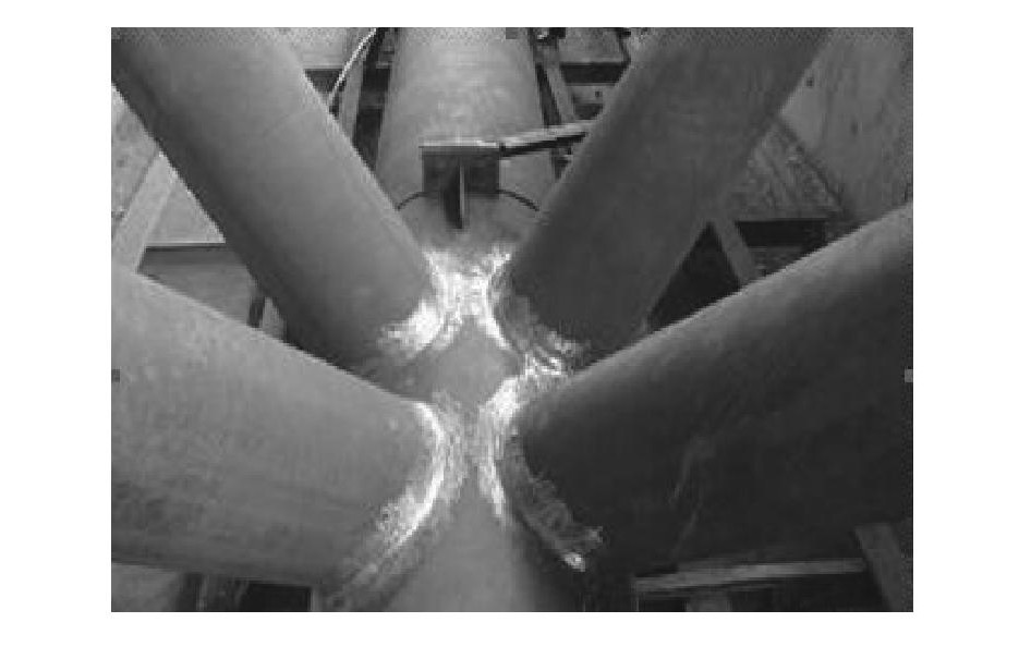
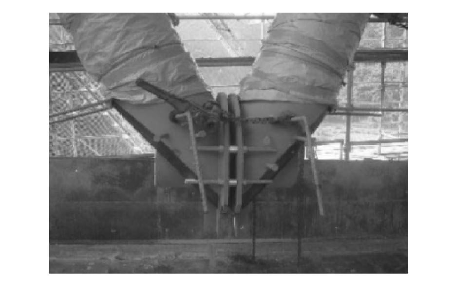
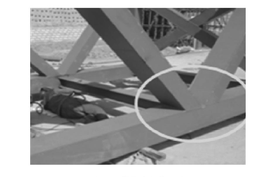
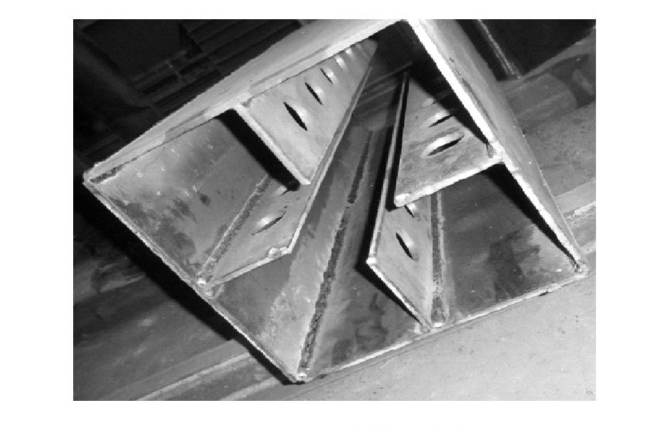
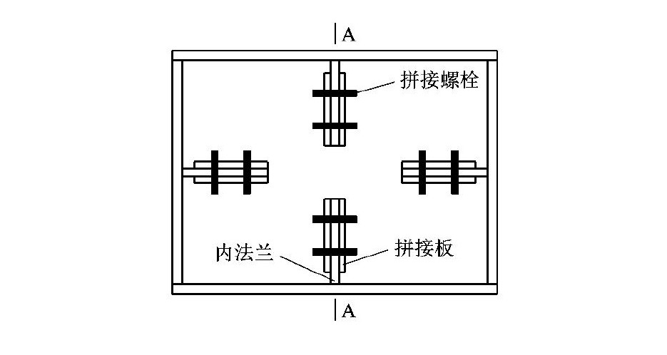
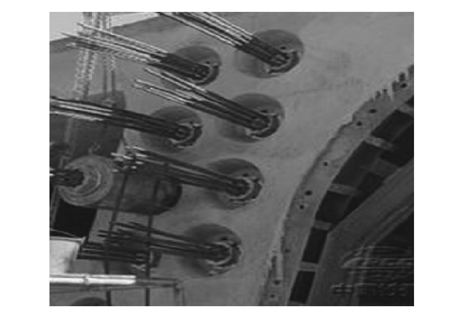
The on-site splicing method between the main truss segment units directly determines the overall construction quality of the main truss. The final selection of the splicing joint between the main truss segment units in this design is a combination of built-in flanges and outer ring welding. This connection method first uses bolts and splicing plates to connect the built-in flanges, smoothly positioning the steel truss segment, and then welding the outer ring steel plate. Compared with previous external flanges, the joint connection of internal flange and outer ring welding is more reliable and aesthetically pleasing(Figure 13、14).
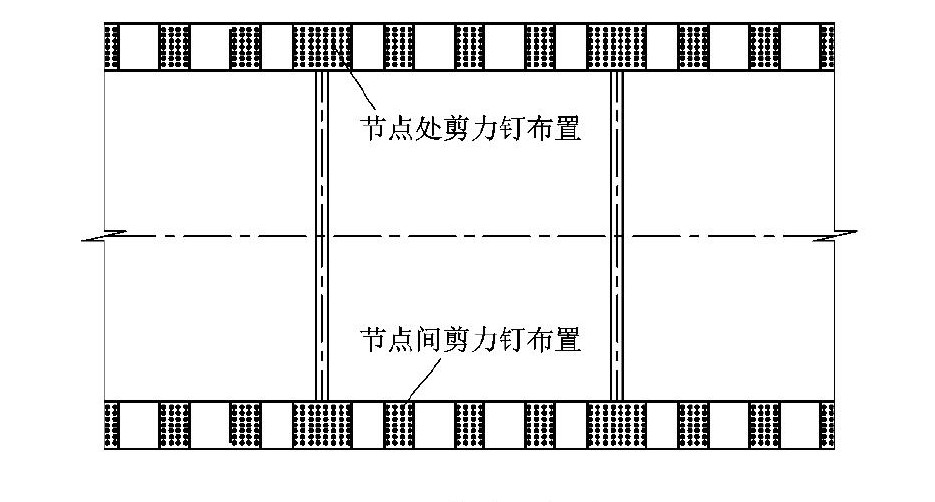
The connection structure between the bridge deck assembly unit and the main truss segment unit is directly related to the combination effect of the bridge deck and the main truss. The connection structure needs to consider the following factors: the truss node is the key structure for structural force transmission. In order to ensure the reliable force transmission of the bridge deck and the upper chord node, shear studs at the transverse wet joint need to be densely arranged(Figure 15)In order to match the shear slots in the bridge deck assembly unit, the shear studs at the main truss corresponding to the shear slots also need to be arranged in groups.


 |
DownLoad:
CSV
Based on the above analysis, the design of tension rods should fully utilize the advantages of good tensile performance of steel, while the design of compression rods should fully utilize the mechanical performance advantages of high compressive bearing capacity of steel-concrete components, while taking into account the insufficient compressive stability of steel pipes.

|
|
 |
DownLoad:
CSV
In summary, based on the initial input seismic force, the seismic performance of rectangular steel-concrete composite truss bridges is significantly better than that of prestressed concrete variable cross-section continuous beam bridges.
Due to the large distance between the two main trusses of the rectangular steel-concrete composite truss bridge, the shear lag effect of the bridge deck is significant. Especially at the fulcrum, the shear force is large and the bridge deck is in tension. The shear lag effect reduces the effective tensile area of the bridge deck. When calculating the crack width of the bridge deck, the effective width of the bridge deck must be considered. In design, the effective width coefficient of the bridge deck is generally used to consider the shear lag effect. The effective width coefficient of the bridge deck is the ratio of the effective distribution width of the bridge deck to the actual width. Taking the 4 × 70m rectangular steel tube concrete composite truss bridge as an example (bridge width 12.75m), the effective width coefficient at the midpoint is calculated based on domestic and foreign standards and finite element analysis.
Table 4Listed the effective width coefficient of the pivot point calculated according to domestic and international standards.
 |
DownLoad:
CSV
The effective distribution width of the bridge deck is
|
|
In the formula:σxNormal stress in the cross-section of the wing edge;σx, maxThe maximum normal stress in the cross-section of the wing edge;beThe effective distribution width of the wing edge;brThe actual width of the wing edge;xCalculate the location of stress points for the bridge deck panel.
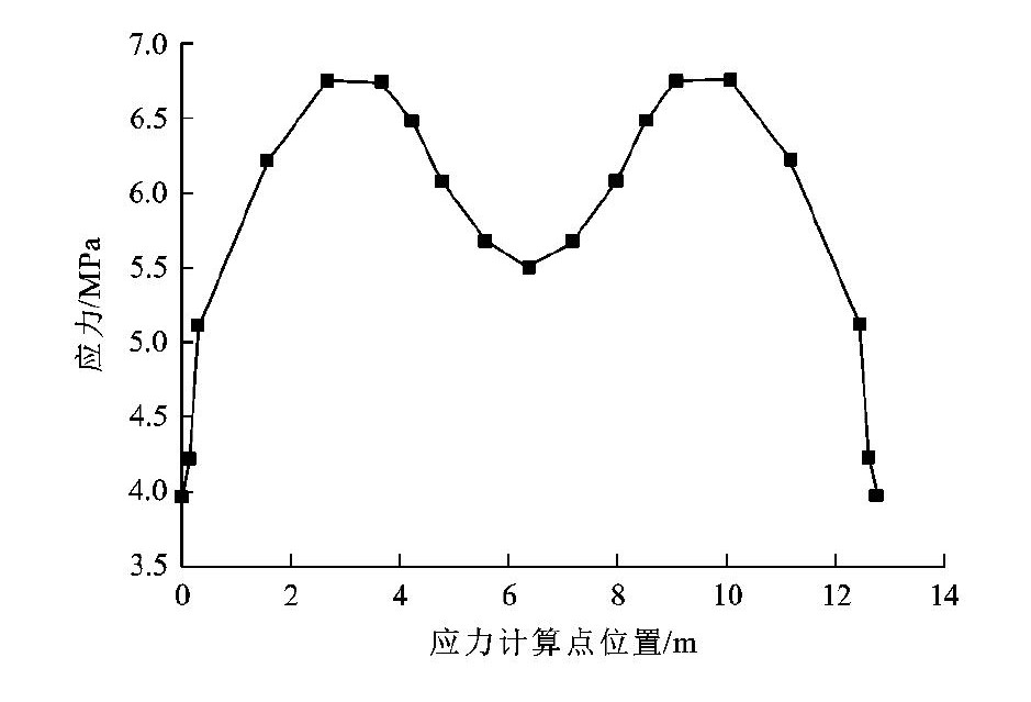
When using the finite element method to analyze the effective width of the bridge deck, the stress and element division size can be calculated based on the transverse division positions of the bridge deck elements, and then approximated using equation (2)
|
|
In the formula:σiFor bridge deck panelsiThe normal stress at the corresponding point of the horizontal block;biFor bridge deck panelsiHorizontal block length;σmaxThe maximum transverse normal stress of the bridge deck.

The stress calculation results of the finite element space model are shown inFigure 21According to equation (3), the effective width coefficient at the fulcrum is 0.899. Compared with the calculation results of domestic and foreign standards, finite element analysis is more targeted, and the calculation results are more accurate and safe. Therefore, the effective width coefficient at the fulcrum in this design is based on the finite element calculation results, and is ultimately taken as 0.899.
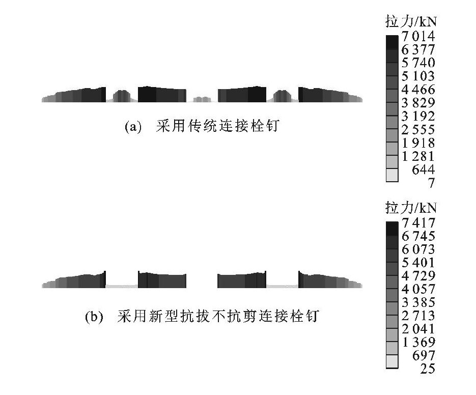
The mechanical performance analysis of the negative bending moment zone has always been a difficult point in the design of steel-concrete composite beams, because in the negative bending moment zone, the concrete bridge deck is under tension, and the concrete itself is prone to cracking. This design adopts partial combination connection technology in the negative bending moment zone - anti pull and non shear connection bolts[27-28]To optimize the mechanical properties of this area. Taking the 4 × 70 m rectangular steel tube concrete composite truss bridge as a calculation example, the mechanical properties of the negative bending moment zone are analyzed.
Comparing the maximum axial tension envelope results of bridge decks under short-term load effect combinations using new anti pull and non shear connection bolts and traditional connection bolts in the negative bending moment zone. causeFigure 22It can be seen that when using the new anti pull and non shear connection bolts, the maximum axial tension of the pier top bridge deck under the short-term load effect combination is 1301kN. When using traditional connection bolts, the maximum axial tension of the bridge deck is 5277N. It can be seen that using the new anti pull and non shear connection bolts in the negative bending moment zone reduces the axial tension of the bridge deck by 75.3%, effectively improving the crack resistance performance of the bridge deck.
Compared with prestressed concrete box girder bridges, rectangular steel tube concrete composite truss bridges use slightly more steel, but significantly less concrete. Therefore, the weight of the upper structure will be greatly reduced, effectively reducing the reinforcement ratio of the bridge piers and the amount of foundation engineering. In addition, the reduction of the weight of the upper structure is very beneficial for the seismic fortification of the lower structure.
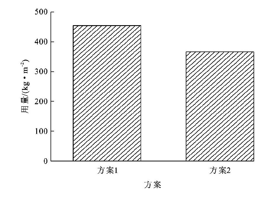
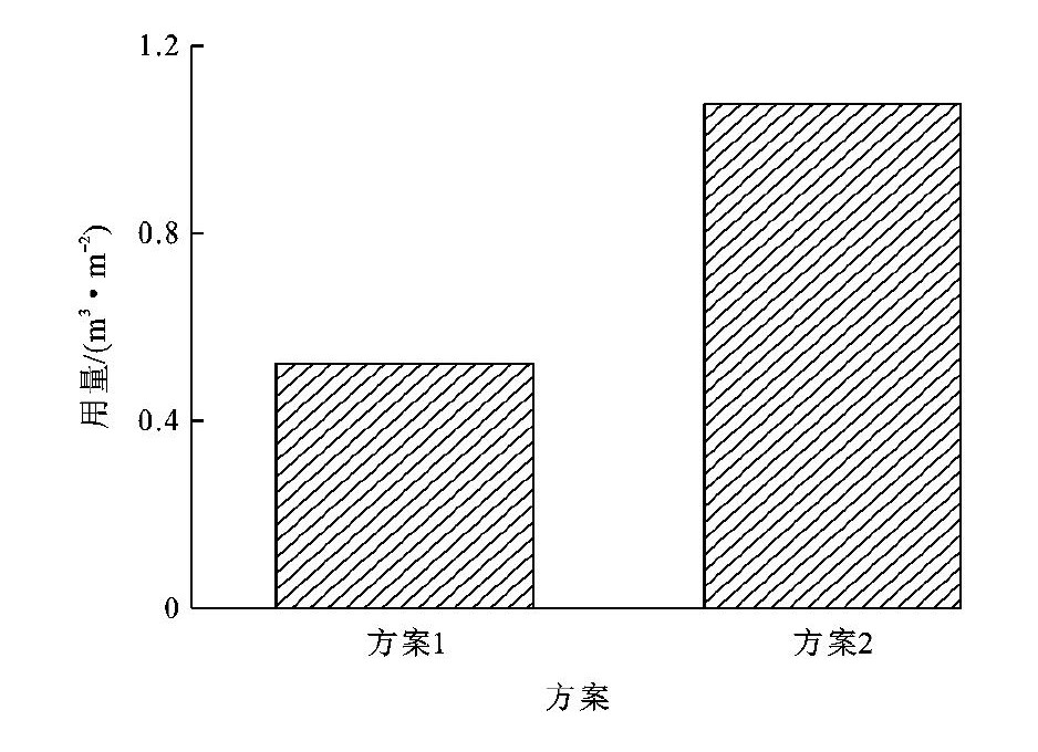
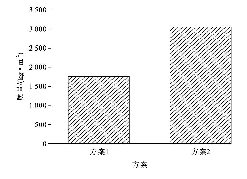
In order to conduct an intuitive economic analysis, a comparison case is now made between Scheme 1 equal section rectangular steel tube concrete composite truss bridge and Scheme 2 variable section prestressed concrete box girder bridge: Scheme 1 has a span arrangement of 4 × 70m=280m, a bridge width of 12.75m, and a main beam cross-section of two main trusses; Scheme 2 has a span arrangement of (50+90+90+50) m=280m, The bridge width is 12.75m, and the cross-section of the main beam is a single box single room.
causeFigure 23~25It can be seen that the ratio of steel consumption, concrete consumption, and upper structure quality between Scheme 1 and Scheme 2 is 1.241, 0.485, and 0.575, respectively. This indicates that compared with the rectangular steel tube concrete composite truss bridge, although the steel consumption is slightly reduced, the concrete consumption and upper structure quality are significantly increased, and the lower structure engineering and foundation engineering also need to be correspondingly increased. The rectangular steel tube concrete composite truss bridge has a lightweight structure, high material utilization rate, low engineering cost, and obvious economic advantages.
Medium span and large-span prestressed concrete box girder bridges generally use cantilever construction method, with complex construction processes such as concrete formwork, steel bar binding, and prestressed tensioning(Figure 26、27)During the construction process, precise monitoring of the structural assembly line shape is required, and the construction period is long. Especially in the western mountainous areas, the collection of sand and stone materials on site during the construction of prestressed concrete box girder bridges can seriously damage the local ecological environment.
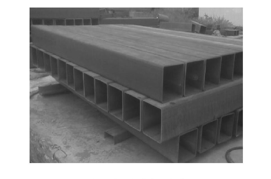
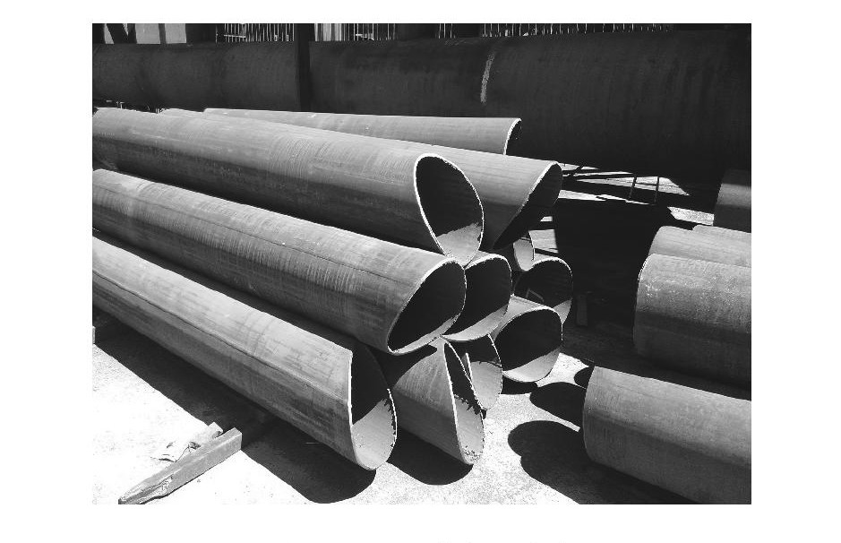
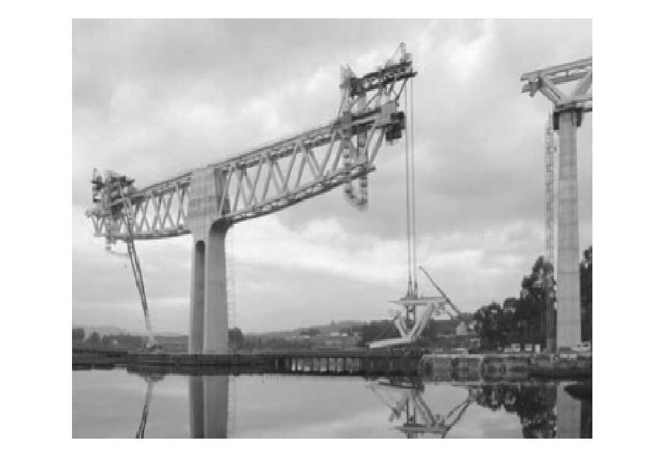
Compared with prestressed concrete box girder bridges, the rectangular steel tube concrete composite truss bridge has a rectangular steel tube truss as the upper main structure, which can be prefabricated in standardized sections in the factory. The quality of component manufacturing is controllable. After the standard prefabricated sections are delivered to the site, they can be assembled conveniently and quickly using cantilever, lifting, and pushing construction methods(Figure 28、29)At the same time, with only a small amount of on-site wet welding work, prefabricated bridge decks and steel main trusses can be assembled through shear studs, and the construction of the upper structure can be fully prefabricated, standardized, and assembled.


(1) A new type of prefabricated bridge structure, the rectangular steel-concrete composite truss bridge, has been proposed, which can provide reference for the design of prefabricated bridges for highways with spans over 50 meters in China.
| [1] |
YAO Bao-qing. Study on control and electromagnetic performance of linear traction motor[D]. Beijing: Beijing Jiaotong University, 2007. (in Chinese)
|
| [2] |
GUO Huan. Direct thrust control and simulation of linear induction motor[D]. Changsha: Central South University, 2007. (in Chinese)
|
| [3] |
LIU Bin-bin, ZENG Jing, LUO Ren, et al. Modeling and dynamics simulation of vehicle with linear induction motor[J]. Journal of Traffic and Transportation Engineering, 2009, 9(5): 37-43, 61. (in Chinese) https://www.cnki.com.cn/Article/CJFDTOTAL-JYGC200905006.htm
|
| [4] |
LIN Jun. Research on the dynamics for LIM vehicle with independent wheel[D]. Chengdu: Southwest Jiaotong University, 2006. (in Chinese)
|
| [5] |
WEI Qing-chao, DENG Ya-shi, FENG Ya-wei. Study of suspension mode influences on LIM metro system dynamic characters[J]. Journal of Railway Engineering Society, 2007(11): 59-64. (in Chinese) https://www.cnki.com.cn/Article/CJFDTOTAL-TDGC200711012.htm
|
| [6] |
KIM D K, KWON B I I. A novel equivalent circuit model of linear induction motor based on finite element analysis andits coupling with external circuits[J]. IEEE Transactions on Magnetics, 2006, 42(10): 3407-3409. doi: 10.1109/TMAG.2006.879078
|
| [7] |
LI Zhong-xiu. Research of eddy current sensor of middle-low speed maglev train[D]. Changsha: National University of Defense Technology, 2006. (in Chinese)
|
| [8] |
LONG Xu-you, WEI Qing-chao, FENG Ya-wei, et al. Dynamic response of linear metro vehicle/track exited by track irregularity[J]. Journal of Traffic and Transportation Engineering, 2008, 8(2): 9-13. (in Chinese) https://www.cnki.com.cn/Article/CJFDTOTAL-JYGC200802005.htm
|
| [9] |
FAIZ J, JAFARI H. Accurate modeling of single-sided linear induction motor considers end effect and equivalent thickness[J]. IEEE Transactions on Magnetics, 2000, 36(5): 3785-3790. doi: 10.1109/20.908365
|
| [10] |
MIRSALIM M, DOROUDI A, MOGHANI J S. Obtaining the operating characteristics of linear induction motors: a new approach[J]. IEEE Transactions on Magnetics, 2002, 38(2): 1365-1370.
|
| [1] | XU Ping, HUANG Qi, XU Tuo, WANG Ao, YANG Cheng-xing, WANG Shi-ming. Data-driven equivalent scaled model of coupler-buffer device design for subway vehicles[J]. Journal of Traffic and Transportation Engineering, 2024, 24(5): 217-233. doi: 10.19818/j.cnki.1671-1637.2024.05.014 |
| [2] | WEN Yong-peng, WU Jun-han, ZHONG Shuo-qiao, ZONG Zhi-xiang, ZHOU Hui. Metro vehicle lateral vibration characteristics based on vehicle-equipment coupling under service conditions[J]. Journal of Traffic and Transportation Engineering, 2024, 24(4): 161-170. doi: 10.19818/j.cnki.1671-1637.2024.04.012 |
| [3] | TAN Fu-xing, SHI Huai-long, WANG Wei, LIU Shi-hui, LIU Hong-tao. High and low temperature characteristics of rubber component dynamic parameters of a bogie[J]. Journal of Traffic and Transportation Engineering, 2019, 19(4): 104-114. doi: 10.19818/j.cnki.1671-1637.2019.04.010 |
| [4] | LIU Shi-hui, SHI Huai-long, WANG Wei, LIU Hong-tao, TAN Fu-xing. Dynamics modelling of positioning rubber joint of a bogie based on physical parameters[J]. Journal of Traffic and Transportation Engineering, 2019, 19(6): 91-100. doi: 10.19818/j.cnki.1671-1637.2019.06.009 |
| [5] | ZHANG Min, FAN Yi-li, MA Wei-hua, LUO Shi-hui. Influence of slip frequency on running performance of maglev vehicle[J]. Journal of Traffic and Transportation Engineering, 2019, 19(5): 64-73. doi: 10.19818/j.cnki.1671-1637.2019.05.007 |
| [6] | CHEN Shi-an, SUN Wen-qiang, WANG Jian, CAI Yu-meng, WANG Jun-cheng. Control of energy-reclaiming semi-active suspension with linear motor based on varying charge voltage method[J]. Journal of Traffic and Transportation Engineering, 2018, 18(2): 90-100. doi: 10.19818/j.cnki.1671-1637.2018.02.010 |
| [7] | JIAO Yun-long, DONG Lei, LIU Xiao-jun, LIU Kun. Spreading features of droplet on micro-textured surface[J]. Journal of Traffic and Transportation Engineering, 2017, 17(4): 98-105. |
| [8] | WEI Qing-chao, XIA Jing-hui, ZANG Chuan-zhen, HAO Min, LIANG Qing-huai. Influence of air gap on dynamic response of LIM metro system[J]. Journal of Traffic and Transportation Engineering, 2017, 17(6): 10-18. |
| [9] | ZOU Rui-ming, MA Wei-hua, LUO Shi-hui. Coupling stability of couplers between locomotive and vehicle[J]. Journal of Traffic and Transportation Engineering, 2016, 16(6): 48-54. |
| [10] | MA Wei-hua, QU Tian-wei, LUO Shi-hui, SONG Rong-rong. Influence of axle-box positioning deviation on partial wear of locomotive wheel flange[J]. Journal of Traffic and Transportation Engineering, 2013, 13(1): 36-41. doi: 10.19818/j.cnki.1671-1637.2013.01.006 |
| [11] | HE Jie, LIU Xia, CHEN Yi-kai, ZHAO Chi-hang. Influence of road condition on running safety in atrocious weather[J]. Journal of Traffic and Transportation Engineering, 2011, 11(1): 58-63. doi: 10.19818/j.cnki.1671-1637.2011.01.010 |
| [12] | WU Lei, ZHONG Shuo-qiao, JIN Xue-song, LI Ling. Influence of polygonal wheel on running safety of vehicle[J]. Journal of Traffic and Transportation Engineering, 2011, 11(3): 47-54. doi: 10.19818/j.cnki.1671-1637.2011.03.009 |
| [13] | LIU Bin-bin, CENG Jing, LUO Ren, WU Ping-bo. Modeling and dynamics simulation of vehicle with linear induction motor[J]. Journal of Traffic and Transportation Engineering, 2009, 9(5): 37-43. doi: 10.19818/j.cnki.1671-1637.2009.05.007 |
| [14] | ZHAO Li-hua, ZHANG Kai-lin, ZHANG Hong-jun. Stress spectrum analysis and fatigue life prediction about wheel axle of high-speed power car[J]. Journal of Traffic and Transportation Engineering, 2008, 8(5): 27-32. |
| [15] | SHAO Yi-ming, HU Yan, XU Jin, YU Zhi-gang. Dynamics system of simulation and identification for road accident black spot[J]. Journal of Traffic and Transportation Engineering, 2008, 8(1): 123-126. |
| [16] | LUO Ren, CENG Jing. Simulation of semi-active and active controls for pantograph-catenary vertical vibrations[J]. Journal of Traffic and Transportation Engineering, 2008, 8(4): 1-6. |
| [17] | LUO Ren, CENG Jing. Active control of pantograph vertical vibration of tilting train[J]. Journal of Traffic and Transportation Engineering, 2006, 6(2): 11-16. |
| [18] | YANG Bin, SUN Qing-hong, HUANG Wen-jie, ZHU Zhuang-rui, DAI Jia-peng, JIANG Yan-qing. Static strength and mode analysis of B-type subway body[J]. Journal of Traffic and Transportation Engineering, 2006, 6(2): 1-5. |
| [19] | LIU Hong-you, YANG Ai-guo. Dynamics performance simulation of double-deck container flat car[J]. Journal of Traffic and Transportation Engineering, 2004, 4(3): 20-24. |
| [20] | WANG Yong, ZENG Jing, LV Ke-wei. Dynamic modeling and simulation of three-piece bogie freieht car[J]. Journal of Traffic and Transportation Engineering, 2003, 3(4): 30-34. |

Figures(9) / Tables(3)
Copyright《Journal of Traffic and Transportation Engineering》编辑部陕ICP备05001904号-1
Address :Editorial Department of Journal of Traffic and Transportation Engineering, Chang 'an University, Middle Section of South Second Ring Road, Xi 'an, Shaanxi(710064) Tel:029-82334388 Email:jygc@chd.edu.cn
All visit:1713422Today's visit:82
Supported by:
Beijing Renhe Information Technology Co. Ltd

LUO Ren, WU Ping-bo, LIU Bin-bin. Constant air gap control simulation of linear induction motor of metro vehicle[J]. Journal of Traffic and Transportation Engineering, 2010, 10(4): 50-57. doi: 10.19818/j.cnki.1671-1637.2010.04.009

|
DownLoad:
CSV
|
DownLoad:
CSV
|
DownLoad:
CSV
|
DownLoad:
CSV

 DownLoad:


 DownLoad: