2022 Vol. 22, No. 6

Display Method:
Review on technical development of Melan method and Melan arch bridges
CHEN Bao-chun, HE Fu-yun, LI Cong, LIU Jun-ping, ŠAVOR Zlatko, MU Ting-min, CHEN Kang-ming, YAO Hai-dong, ZHANG Meng-jiao
Abstract:

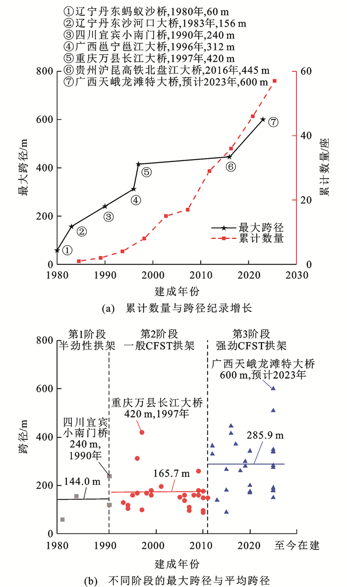
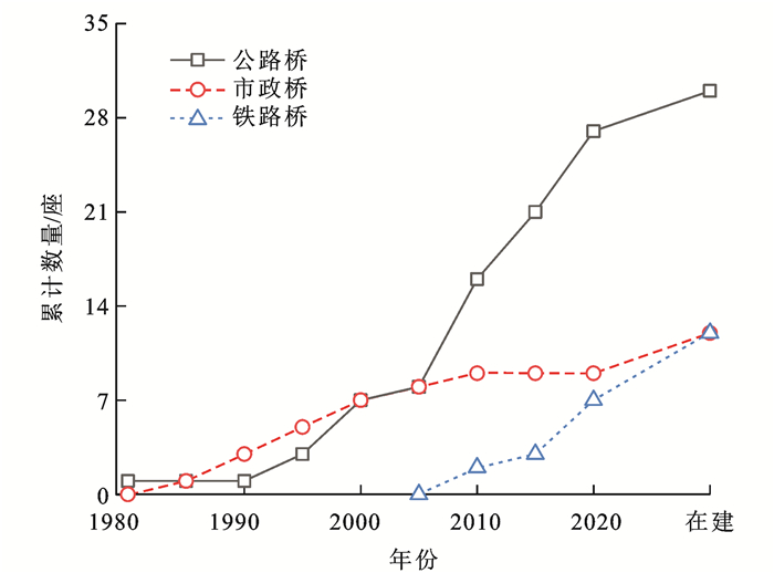
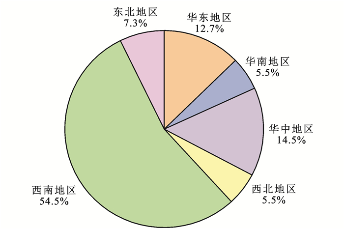
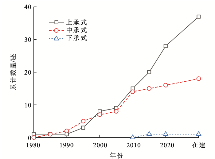
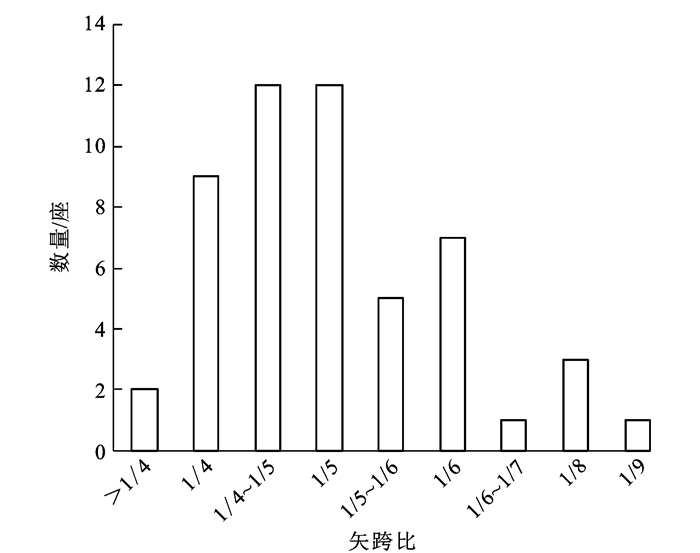
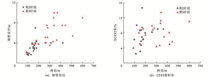
The development process of the Melan method for more than 100 years was reviewed, and the corresponding technical terms as well as their connotations and denotations were discussed. The application status of Melan arch bridges in China was investigated and analyzed, and the key technical issues and the development experience of the Melan method were summarized. The research status and development direction of the techniques employed in the Melan method and Melan arch structure were clarified. Research results show that the Melan method originated from Europe and America in the late 19th century and at the beginning of the 20th century, and then it was spread to China and Japan in the second half of the 20th century. Its development in China can be divided into three stages according to the types of embedded arch frameworks: semi-stiff arch framework, (general) concrete-filled steel tubular (CFST) arch framework, and strong CFST arch framework. The Melan arch bridge is a kind of concrete arch bridge. The embedded arch framework used by the Melan method is mainly for the construction, while its reinforcement effect on the concrete is auxiliary after the bridge is completed. A total of 57 Melan arch bridges were built or under construction in China by May 2021. All concrete arch bridges in China with a span of greater than 250 m are built with this method since 2007, of which the largest span is 600 m. The Melan arch bridge is mainly applied in highway bridges in mountainous areas of southwest China, and its application in railway bridges increases significantly in recent years. The deck bridges with braced twin ribs are mainly applied. The rise-to-span ratio is concentrated in the range of 1/4-1/6, and the catenary is widely used as the arch axis. The area ratio of cross-section of the embedded CFST arch to the cross-section of the main arch, the diameter of steel tube, and the strengths of steel tube and concrete materials increase with time and the rise in span. In the application of the Melan method, three factors should be comprehensively considered, namely, the limited steel consumption, controlled mechanical behavior of the structure, and simple construction. The embedded arch framework developes from the earliest section steel to the truss-like structure and then to the box section and truss structure. The truss structure is commonly used today. The cantilever method is mostly used in the erection of the steel-tube truss structure, and the swing method is also used in various forms. To reduce the steel consumption and control the structural stress and deformation during the construction, the CFST truss structure is innovatively introduced as the embedded arch framework in China, and the load adjustment methods are adopted, including preloading, auxiliary anchor cables, multi-point balanced pouring, and stay cables. In recent years, the pouring ring number for the encased concrete in the cross-section significantly reduces to three or less due to the application of the strong CFST arch framework. In terms of the application of the Melan method, the researches on materials, structure, and construction technology focusing on the strong CFST arch framework should be further conducted. Regarding the Melan arch structure, the researches on the mechanical performance of steel-tube-reinforced concrete structures, ultra-high-performance materials, and steel web(rod)-concrete composite arches should be strengthened. Meanwhile, the durability of the Melan arch bridge should be thoroughly explored for the design of new bridges and the repair as well as the maintenance of existing bridges. 5 tabs, 18 figs, 85 refs.

More>
2022, 22(6): 1-24. doi: 10.19818/j.cnki.1671-1637.2022.06.001
Research progress of seismic resilient girder bridges at home and abroad from WCEE
JIA Jun-feng, WEI Bo, DU Xiu-li, GUO Bin-li, GUO He
Abstract: The relevant research progress of seismic resilient girder bridges presented on the 16th and 17th World Conference on Earthquake Engineering (WCEE) was sorted and summarized. Specifically, the latest research progress of post-tensioned prestressed rocking self-centering girder bridges and other novel seismic resilient girder bridge systems was analyzed. The research on the application of high-performance materials in resilient girder bridges was summarized, and the engineering application of self-centering girder bridges at home and abroad was outlined. The research on the replaceable devices, such as self-centering energy dissipation devices and displacement-limiting devices, in seismic resilient girder bridge structures was presented. The seismic performance of girder bridge structures with additional replaceable devices was discussed. The evaluation methods for the seismic resilience of a single girder bridge and that of a bridge network were reviewed. The research orientation and development trend of seismic resilient girder bridge structures were explored. Research results show that, the post-tensioned prestressed self-centering girder bridges with additional replaceable energy dissipation devices are the most widely studied seismic resilient girder bridge structures, and a number of demonstration projects have been completed. The performance of this type of structure in strong earthquakes remains to be verified by actual earthquakes. In terms of replaceable devices, new structures and new configurations of replaceable devices should be developed by availing high-performance materials. On this basis, reasonable technologies for connecting such devices with bridges and seismic design methods can be investigated. In addition, the completed girder bridges in China are faced with outstanding issues in developing seismic resilience evaluation methods, capacity enhancement technologies, and design theories for existing girder bridge structures under consideration of the influences of multiple factors, such as performance degradation and demand increase.More>
2022, 22(6): 25-45. doi: 10.19818/j.cnki.1671-1637.2022.06.002
Review on research of anti-overturning of highway bridges with single-column piers
ZHOU Yong-jun, WANG Ye-lu, ZHAO Yu, XUE Yu-xin, HAN Zhi-qiang
Abstract: To promote the sustainable development of highway bridges with single-column piers, the typical bridge overturning accidents at home and abroad were summarized. The research progress of highway bridges with single-column piers in the field of anti-overturning was systematically stated from three aspects: bridge overturning failure mechanism, influencing factors of overturning stability, and control methods for anti-overturning. The serious threat of overload to bridge structrue safety and the complexity and urgency of the overturning problem were emphasized. Research results show that bridge overturning accidents are mostly induced by eccentric overloaded vehicles, and the phenomenon of strong bending and weak overturning exists in these bridges with single-column piers. It is urgent to establish a calculation standard for heavy vehicle loads suitable for the bridge anti-overturning analysis due to different effects of vehicle loads on the bending moment, shear force, and torque moment of bridges. The overturning failure modes and the corresponding most unfavorable load states vary in terms of different bridges, and it is important to clarify the overturning axis mechanics models for the evolution of the most unfavorable overturning states of different failure modes, and the research should be intensified on the overturning axis mechanics models and the most unfavorable overturning states. The mechanism of bridge overturning under the coupling effect of temperature, prestress, shrinkage-creep, and bearing settlement is still unclear. Using the most unfavorable state of reaction force to describe the overturning limit state of the bridge ignores the mechanical connection between the overturning effect and the torque moment characteristics. It is suggested that the overturning failure modes and reasonable overturning axis mechanical models should be combined based on the reliability theory to improve the anti-overturning control calculation method, so as to reduce the safe operation risk of highway bridges with single-column piers. Under a certain extent of safety redundancy of anti-overturning and monitoring and maintaining of bridges, strengthening the management of overloads is the fundamental way to prevent such accidents. 2 tabs, 12 figs, 104 refs.More>
2022, 22(6): 46-66. doi: 10.19818/j.cnki.1671-1637.2022.06.003
Digital fatigue test of detail group at deck-U rib-diaphragm access hole of steel bridge deck in cable-stayed bridge
WANG Chun-sheng, MAO Yu-bo, LI Pu-yu, ZHU Chen-hui
Abstract: To investigate the fatigue crack propagation mechanism of steel bridge deck in cable-stayed bridges under the multi-field coupling effect, a model for the multi-scale digital fatigue test of the whole cable-stayed bridge was constructed. The entire welding process of the multi-pass welds at the detail group at the deck-U rib-diaphragm access hole was simulated to introduce the welding residual stress into the model for the digital fatigue test. The digital fracture parameter analysis and the digital fatigue test were conducted under the multi-field coupling effect by the extended finite element method to clarify the propagation mechanism and propagation behavior of typical fatigue cracks of the detail group at the deck-U rib-diaphragm access hole. Research results show that the high residual tensile stress can be observed at the detail group at the deck-U rib-diaphragm access hole, with a maximum being close to the yield strength of steel. The influence of the welding residual stress on the fatigue performance of the steel bridge deck cannot be ignored. Subsequent welds affect the stress field distribution in the existing weld area. Therefore, the entire welding process needs to be simulated when the welding residual stress field in the influence range of multi-pass welds is analyzed and calculated. Under the multi-field coupling effect of dead-load stress field, live-load stress field and welding residual stress field, the maximum equivalent stress intensity factor ranges of four typical types of fatigue cracks of the detail group at the deck-U rib-diaphragm access hole are all larger than the fatigue crack propagation threshold according to the engineering criterion for the propagation of mixed cracks. In this case, the four types of fatigue cracks all propagate under the cyclic fatigue loading. Under the multi-field coupling effect, the fatigue cracks initiating from the deck-side weld toe of the deck-to-U rib welded joint above the access hole and those initiating from the U rib-side weld toe of the U rib-to-diaphragm welded joint are all mixed cracks of modes Ⅰ, Ⅱ, and Ⅲ dominated by mode-Ⅰ cracks. Nevertheless, the influences of mode-Ⅱ and mode-Ⅲ cracks cannot be overlooked. The fatigue cracks initiating from the deck-side weld root of the deck-to-U rib welded joint above the access hole and those initiating from the edge of the diaphragm access hole are all mode-Ⅰ cracks. The muti-scale digital fatigue test constructed under the multi-field coupling effect can provide analysis and simulation methods for the fatigue crack propagation in the steel bridge deck of a long-span bridge in operation. 1 tab, 28 figs, 32 refs.More>
2022, 22(6): 67-83. doi: 10.19818/j.cnki.1671-1637.2022.06.004
A Fe-SMA-based fabricated active reinforcement method for fatigue cracks in steel bridge decks
BU Yi-zhi, AN Lang, CUI Chuang, HU Ji-dan, ZHANG Qing-hua, ZHU Jin-zhu
Abstract: A new fabricated active reinforcement method for fatigue cracks in steel bridge decks based on iron-based shape memory alloy (Fe-SMA) was proposed to achieve the rapid reinforcement of the steel bridge decks. The safety and reliability of the reinforcement system were verified by the calculation results of the finite-element refined double-sided reinforcement model and the observation of the preliminary activating and loading test. On this basis, the fatigue cracks in the U-rib butt weld were taken as the research object, the linear elastic fracture mechanics was involved, the stress and cracking characteristics of the fatigue details were considered, the amplitude of the stress intensity factor of mode-Ⅰ cracks at the tips of surface and internal cracks under cyclic loading was used to evaluate the reinforcement effect of the reinforcement system, and the specific reinforcement schemes for cracks with different lengths were determined. Analysis research results show that the amplitude of the stress intensity factor of the crack tips can be reduced to below the propagation threshold by the Fe-SMA-based active reinforcement method for fatigue cracks in steel bridge decks, and can effectively restrain the further propagation of fatigue cracks. The non-penetrating fatigue cracks shorter than 50 mm can be reinforced by the Fe-SMA with a width of 60 mm, and the stress intensity factor of the points of concern at the crack tips reduces by more than 90%. The 50-120 mm long penetrating fatigue cracks can be reinforced by the Fe-SMA with a width of 120 mm. The fatigue cracks with a length of 120-350 mm need to be reinforced simultaneously by bottom plates and webs. The desired crack-arresting state is achieved invariably. 2 tabs, 19 figs, 30 refs.More>
2022, 22(6): 84-94. doi: 10.19818/j.cnki.1671-1637.2022.06.005
Test on robustness strengthening for suspended deck system in half-through and through arch bridges
CHEN Kang-ming, WU Qing-xiong, LUO Jian-ping, CHEN Bao-chun, HUANG Jian-hua
Abstract: To enhance the robustness of the suspended deck system of half-through and through arch bridges, the suspended deck system of half-through and through arch bridges without a stiffening girder in the longitudinal direction of the bridges was taken as the research object, a robustness strengthening structure with a steel tubular truss (STT) stiffened longitudinal girder was proposed for the suspended deck system, and a comparative analysis was made on the dynamic responses of the remained structures at the moment of hanger fracture before and after the robustness strengthening of the suspended deck system. A test and a finite element analysis were conducted on the model of the robustness strengthening structure with an STT stiffened longitudinal girder, and the mechanical performance and failure mode of the strengthened structure after the hanger fracture were studied. The effects of the preload of finish-rolled screw-thread steel bar, the thickness of perforated steel plate, and the material on the mechanical performance of the robustness strengthening structure were discussed. Research results show that after the suspended deck system is strengthened by the STT stiffened longitudinal girder, the maximum vertical displacement and stress of the deck system reduce by 1.30(1.31) and 3.31(1.99) times, respectively, when the long (short) hanger fractures. The maximum cable force of the hanger adjacent to the fractured one reduces by 1.25 (1.25) times. In the elastic-plastic stage, the perforated steel plate of the structure strengthened by the STT stiffened longitudinal girder is subjected to bending deformation, and the embedded steel rebar near the bottom of the cross beam is damaged. When the ultimate load is reached, a crack appears on the weld between the middle-lower stiffened steel plate and the perforated steel plate. Then, a crack appears on the weld between the lower chord and the perforated steel plate, and the carrying capacity is thereby lost. The reasonable preload of the finish-rolled screw-thread steel bar is 50 kN, and the reasonable thickness of the perforated steel plate is 20 mm. The ultimate load of the strengthened structure increases by 11.9% when the material of the perforated steel plate is updated from Q235 to Q345. This indicates that enhancing the material strength of the perforated steel plate can effectively improve the ultimate bearing capacity of the strengthened structure. To sum up, utilizing the STT stiffened longitudinal girder to reinforce the suspended deck system in half-through and through arch bridges can effectively strengthen its robustness.More>
2022, 22(6): 95-113. doi: 10.19818/j.cnki.1671-1637.2022.06.006
Diagonal cracking mechanism and reinforcement design method of bridge decks in cable-girder anchorage zone of composite girder cable-stayed bridge
MENG Jun-miao, LIU Yong-jian, WANG Xing
Abstract: In order to reveal the cracking mechanism of diagonal cracks in the cable-girder anchorage zone during the cantilever erection of a composite girder cable-stayed bridge, the distribution characteristics of shear stress and normal stress of bridge decks in the zone were analyzed starting from the actual stress state. The formation cause and morphological characteristics of the cracks were obtained in light of the stress Mohr's circle theory. Depending on the relevant codes and truss model, the measures against cracks through the design of diagonal reinforcement and L-shaped reinforcement were proposed. The Taizhou Bay Oversea Bridge was taken as an example to verify the stress distribution characteristics of the bridge decks in the anchorage zone and the effectiveness of the reinforcement methods. Research results show that the in-plane shear stresses of the bridge decks in the anchorage zone are mainly provided by the vertical and horizontal components of the cable force during the cantilever erection. The normal stresses in the longitudinal and transverse directions of the bridge are mainly provided by the overall bending moment of the cable-stayed bridge due to the load from the lifting weight, the local negative bending moment caused by the increase of the cable force, and the local pressure. Among these stresses, the increase of the normal stress in the longitudinal direction of the bridge is the main reason for the increase of the principal tensile stress in the cable-girder anchorage zone. When the principal tensile stress is greater than the tensile strength of the concrete, bridge decks have a great risk of diagonal cracking. Considering the effect of local pressure, cracks generally first appear at the top of bridge decks near the cable-girder anchor point. When gradually away from the anchorage zone, the influences of local negative bending moment and local pressure decreases, thus the normal stress at the top plate of bridge decks, and the principal tensile stress, and the included angle between the development direction of the crack and the longitudinal direction of the bridge becomes smaller gradually. At the same time, the normal stress of the bottom plate of bridge decks changes from compressive stress to tensile stress, and the principal tensile stress increases, which enhances the possibility of crack penetration. With the use of the truss model of diagonal cracking of concrete slab, the L-shaped crack-resistant reinforcement is deployed in the cable-girder anchorage zone. The maximum principal tensile stress of the top plate reduces by 1.26 MPa, in which the maximum normal stress in the longitudinal direction of the bridge reduces by 0.91 MPa, and the in-plane shear stress reduces by 0.50 MPa. Therefore, the crack-resistant reinforcement is capable of resisting bending and shear to some extent.More>
2022, 22(6): 114-129. doi: 10.19818/j.cnki.1671-1637.2022.06.007
Mechanical performance and design calculation method of prefabricated voided slab bridge with transverse post-tensioning
WU Qing-xiong, HUANG Wan-kun, WANG Qu, CHEN Kang-ming, CHEN Bao-chun
Abstract: In order to improve the crack load and failure load of the hinge joint junction surface and solve the problem of the transverse force of the voided slab bridge, the mechanical performance of the prefabricated voided slab bridge with transverse post-tensioning (TPT)was studied. The mechanical mechanism of the hinge joint junction surface was analyzed by a local model test. The full-scale model test was adopted to research the overall mechanical performance of the voided slab bridge. Based on the mechanical mechanism of the hinge joint junction surface, the upper and lower limits of TPT were determined, and the design calculation formula of TPT was put forward. Test results show that the normal and tangential bonding strengths of the junction surface with TPT are 1.40-1.45 and 0.50-0.62 MPa, respectively, which are 8.1%-12.5% and 12.4%-38.3% higher than those without TPT, respectively. Moreover, increasing TPT can improve the normal and tangential bonding strengths of the junction surface. The failure mode of the full-scale test model of the voided slab bridge with TPT is the cracking failure of the voided slab, and no hinge joint cracking occurs during the test. The application of TPT can improve the transverse connection among slabs, avoid the loss of the transverse load transmitting ability due to the hinge joint junction surface damage and the failure of the structure, and increase the ultimate load of the voided slab bridge. The proposed formula for TPT design can effectively calculate the design value of TPT of the voided slab bridge.More>
2022, 22(6): 130-142. doi: 10.19818/j.cnki.1671-1637.2022.06.008
Flexural performance of HSS-UHPC composite beams with perfobond strip connectors
HE Shao-hua, YANG Gang, FANG Teng-peng, YANG Jia-liang
Abstract: Considering the influence of different shear connection degrees, the mid-span two-point symmetrical loading tests for three pieces of high strength steel (HSS)-ultra-high performance concrete (UHPC) composite beams using perfobond strip (PBL) connectors were conducted to evaluate the flexural performance of HSS-UHPC composite beams. The properties including flexural rigidity, deflection, interfacial slip, and strain distribution laws of HSS-UHPC composite beams were analyzed under the shear connection degree of 1.02, 0.89, and 0.76, and the overall performance of steel beams and UHPC plates was discussed. In addition, the failure mechanisms of the beams subjected to bending moments were analyzed. On the basis of the ABAQUS nonlinear finite element numerical models for the HSS-UHPC composite beams, the matching relationships among concrete strength, plate thickness, and steel strength were investigated, and the feasibility of existing simplified plasticity theory in calculating the flexural performance of the HSS-UHPC composite beams was evaluated. Research results indicate that the HSS-UHPC composite beams using PBL connectors have the favorable flexural capacity and large plastic deformability, and their flexural rigidity and ductility are qualified for engineering applications. For the composite beams in the elastic stage, the relative interfacial slip between UHPC and HSS develops slowly, and the maximum slip occurs near the 1/8 of the beam. In the plastic stage, the interfacial slip rises rapidly, and the maximum slip section gradually moves to the beam ends. The flexural performance of HSS-UHPC composite beams is significantly affected by the shear connection degree. When the connection degree decrease from 1.02 to 0.89 and 0.76, the initial flexural rigidity of the composite beams lowers by 7.0% and 8.7%, respectively, and the corresponding ultimate bearing capacity decreases 9.2% and 14.6%, but the maximum slip grows by 15.8% and 17.0%, respectively. Good agreement is found among the numerical, experimental, and theoretical results. Numerical result demonstrates that after the replacement of Q460 steel with Q690 steel for the composite beams, the flexural capacity sees an increase of 29.0%, but the ductility decreases by 39.7%. The ductility and flexural capacity of the HSS-UHPC composite beams can be improved by higher UHPC strength and thicker concrete plates.More>
2022, 22(6): 143-157. doi: 10.19818/j.cnki.1671-1637.2022.06.009
Interfacial force transfer mechanism of concrete-filled steel tube based on field truss bridge test
CHENG Gao, ZHANG Zhi-heng, XIE Liang, JI Zi-tian
Abstract: To analyze the bearing performance of concrete-filled steel tubular truss bridge and steel-concrete composite action mechanism, the field truss bridge test on the interfacial force transfer behavior of concrete-filled steel tubes for the upper and lower chords and the finite element parameter analysis of shell and solid elements of the bridge were carried out. On the basis of the simply-supported half-through steel truss bridge with a main span of 71 m, 102 strain measuring points were arranged within the joint range along the upper and lower chords. The characteristics of axial strain distributions of steel tubes and the interfacial force transfer between steel and concrete were tested and analyzed under the action of the loading vehicle. The software ABAQUS was used to build the finite element model for the shell and solid elements of the test bridge, and the model reliability was verified by the measured deflection and strain. After that, the influences of parameters such as the interfacial connection state, interfacial shear stiffness, steel tube thickness, and concrete strength in the tube on the interfacial force transfer performance of concrete-filled steel tubes were analyzed. Analysis results show that the axial strain distribution laws of steel tubes can reflect the basic characteristics of the interfacial force transfer of the concrete-filled steel tube. The uneven distributions of interfacial shear force are shown in the joint areas of the upper and lower chords of the concrete-filled steel tubular truss. The axial strain of steel tubes at the steel-concrete interfaces within the effective force transfer range is distributed as a negative exponential function. In other areas, it remains unchanged. For the fully de-bonded chords of the concrete-filled steel tubular truss, the axial strain distribution of steel tubes is a quadratic function in a certain range of joints. As a result, the different axial strain distribution laws of steel tubes due to the interface connection state and the shear transfer length can be used to evaluate the steel-concrete composite action strength and interfacial working state between the concrete and the steel tube. The shear transfer length of the truss chord becomes longer with the increases in the steel tube thickness and strength of concrete in the tube, but the influence of steel tube thickness is more significant. Setting shear connectors in the chord of concrete-filled steel tubular truss can shorten the shear transfer length.More>
2022, 22(6): 158-168. doi: 10.19818/j.cnki.1671-1637.2022.06.010
Mechanical property of improved hinge joint junction surface in prefabricated voided slab bridge
HUANG Wan-kun, WU Qing-xiong, WANG Qu
Abstract: In order to improve the transverse mechanical property of prefabricated voided slab bridges, two hinge joint improvement methods were designed. Specifically, discontinuous steel bars could be replaced by continuous steel plates in hinge joint junction surfaces, and improved hinge joint structures and grouting materials could be used. A local model test method was adopted, and the normal and tangential strengths of the hinge joint junction surface were calculated. The formulas for calculating the flexural and shear capacities of the hinge joint junction surfaces with discontinuous steel bars and continuous steel plates were proposed. Research results indicate that the errors between the test values of local model and the calculation values from the proposed formula for calculating the flexural and shearing capacities are less than 10%, so it is proved that the proposed formula can accurately calculate the bearing capacities of hinge joint junction surface with continuous steel plate. For full-depth hinge joints without steel bars in junction surfaces, the normal strength of the junction surface is 1.29 MPa, which is 39% the axial tensile strength of weak side concrete. The tangential strength of the junction surface is 0.45 MPa, which is 1.5% the axial compressive strength of the weak side concrete. Compared with the hinge joint without steel bars in junction surface, the normal strengths of the hinge joint junction surfaces with discontinuous steel bars and continuous steel plates increase by 98% and 73%, respectively, and the tangential strengths of the junction surfaces increase by 71% and 78%, respectively. The normal strength of partial-depth hinge joint junction surfaces with normal concrete is 1.30 MPa, which is 40% the axial tensile strength of the weak side concrete. The tangential strength of the junction surfaces is 0.33 MPa, which is 1.1% the axial compressive strength of the weak side concrete. Compared with the junction surfaces with normal concrete grouting full-depth and partial-depth hinge joints, the normal strengths of the junction surfaces with UHPC grouting full-depth and partial-depth hinge joints improve by 13% and 21%, respectively, and the tangential strengths of the junction surfaces improve by 64% and 94%, respectively. 6 tabs, 15 figs, 32 refs.More>
2022, 22(6): 169-181. doi: 10.19818/j.cnki.1671-1637.2022.06.011
Temperature load and effect analysis of asphalt mixture combustion on steel box girder bridge deck
LI Yang, WANG Zuo-cai, WANG Chang-jian, HAN Guang-zhao
Abstract: In order to study the thermal effect of steel box girder and bridge deck pavement under the action of fire, a small-scale steel deck combustion experiment bench was established. The temperature data of the top surface, middle surface, and bottom surface of an asphalt pavement layer under the action of fuel fire were obtained. According to the temperature data of the top surface, a temperature-time curve based on the data of the combustion experiment was fitted and compared with ISO 834 standard temperature-time curve, and the temperature field of the small-scale experiment was verified by numerical simulation. A finite element model of a steel box girder bridge with a size of 11.25 m×3.60 m was established. The stress and deformation characteristics of the bridge under working conditions with midspan, pedestal, and full-span fire were extracted. Research results show that the temperatures in the middle and bottom of the two-dimensional numerical simulation specimens at 260.70 ℃ and 89.38 ℃ are similar to the test data at 248.9 ℃ and 82.59 ℃ under the action of the experimentally fitted temperature-time curve, and their heating trends are relatively consistent, which indicates that the temperature field simulation results are reliable. The maximum temperature drop of the steel box girder roof in the fire load area is 60.91%, which suggests that the asphalt mixture pavement layer can block the transmission of temperature to a certain extent. The maximum Mises stress on the steel box girder under working conditions with midspan and pedestal fires appears in the cold-hot alternate region where the fire load spreads to the low-temperature area. The upward deformation occurs in the fire load area under the midspan fire working condition, while the upward and downward deformations both occur in the fire load area and midspan area under the pedestal fire working condition. The Mises stress distribution under the full-span fire working condition is relatively uniform, and the downward deformation in the midspan is serious. Under the three fire modes, the stress and deformation data based on the experimentally fitted temperature-time curve are lagging behind and lower than ISO 834 standard temperature-time curve. 5 tabs, 15 figs, 30 refs.More>
2022, 22(6): 182-192. doi: 10.19818/j.cnki.1671-1637.2022.06.012
Running safety of hybrid rigid frame railway bridge with double-deck combined steel truss during earthquakes
GOU Hong-ye, PENG Ye, LI Liang, WANG Jun-ming, PU Qian-hui
Abstract: A hybrid rigid frame railway bridge with a double-deck combined steel truss was taken as the engineering background to investigate the running safety of long-span bridges during earthquakes in special areas. A train-track-bridge coupled vibration analysis model was established by taking into account material nonlinearity, tangential friction, and accurate wheel-rail Hertzian contact relationship. In addition, the application of random irregularities of the rails was realized on the basis of the secondary development of ABAQUS-Python software. The EL Centro seismic wave was selected as the input excitation to analyze the damage evolution laws of the hybrid rigid frame bridge with a double-deck combined steel truss under the action of a strong earthquake. The dynamic response indexes under different earthquake intensities and different train speeds were calculated, including the train derailment coefficient, wheel load reduction rate, and train body vibration acceleration. The influence laws of key parameters on the running safety of the bridge during earthquakes were revealed, and the train speed limit based on the running safety was proposed for the hybrid rigid frame bridge. Research results show that the plastic damage in different degrees occurs on each component of the bridge under a rare earthquake (0.38g), the bridge piers are damaged in large areas, and the bridge still has a certain bearing capacity after the earthquake. The train derailment coefficient during the earthquake rises significantly with the increase in the earthquake intensity. The maximum train body vibration acceleration presents an approximately linear increase with the earthquake intensity. The wheel load reduction rate of a train is the key control indicator to the running safety, and its peak value is positively correlated with the train speed. The wheel load reduction rate of a train exceeds the limit, and wheel-rail separation occurs for a long time at the moment when the train gets off the bridge under the train speed of 200 km·h-1 and the earthquake intensity greater than 0.10g. The safe speed is 160 km·h-1 under 0.20g design earthquake from the perspective of running safety. 2 tabs, 13 figs, 30 refs.More>
2022, 22(6): 193-206. doi: 10.19818/j.cnki.1671-1637.2022.06.013
Wind-induced vibration performance of suspended double-deck closed box girder bridge deck
LI Jia-wu, HONG Guang, WANG Jun, WANG Jia-ying, WANG Feng, LI Yu
Abstract: A suspended double-deck closed box girder bridge deck was taken as the research object, and the influences of structural static coupling and aerodynamic interference on the wind-induced vibration performance of the bridge deck were studied through a wind tunnel test. The variational mode decomposition method was used to perform the mode decomposition on experimental monitoring signals and identify flutter modes. A vibration morphology vector diagram and a phase diagram were used to analyze the coupling degree of flutter bending and torsion and the phase difference of the bending and torsion. Flutter derivatives were identified by the least square method, and the aerodynamic damping of the flutter was identified by the flutter derivatives based on the incentive-feedback principle. Research results show that under the joint action of structural static coupling and aerodynamic interference, soft flutter occurs on the lower section, and the vertical and torsional vibration participation coefficients are 0.85 and 0.53, respectively. The flutter morphology tends to be a vertical vibration morphology. The lower section flutters under the action of self-excited aerodynamic force, and the decrease in the phase difference of the self-excited aerodynamic force makes the phase difference of the flutter bending and torsion reduce to 81.29°. However, the upper section performs a forced vibration under the action of a structural coupling force, and the phase difference of the bending and torsion of the upper section is determined to be 100.81° under the influence of the phase difference of the structural coupling force. The aerodynamic damping of the vertical vibration in the lower section mainly comes from the negative damping of a self-excited lift force of vertical velocity and the negative damping of a coupled lift force generated by the bending and torsional velocity through the incentive and feedback, which account for 60% and 40%, respectively. The aerodynamic damping of the torsional vibration in the lower section mainly comes from the positive damping of a self-excited lift force torque of torsional velocity and the positive damping of a coupled lift force torque generated by the bending and torsional velocity through the incentive and feedback, which account for 45% and 50%, respectively. Therefore, for the suspended double-deck closed box girder bridge deck, the soft flutter of the lower section is inclined to the vertical vibration morphology under the aerodynamic negative damping drive of the vertical vibration, and the soft flutter of the lower section induces a soft flutter with a bending-torsional coupling of the vibration system for the suspended double-deck bridge deck. 1 tab, 17 figs, 35 refs.More>
2022, 22(6): 207-219. doi: 10.19818/j.cnki.1671-1637.2022.06.014
Active blowing flow control for VIV of streamlined box girder and its mechanism
LI Chun-guang, YAN Hu-bin, HAN Yan, MAO Yu, LUO Chu-yu
Abstract: In order to analysis the effect of flow vibration suppression measures based on active blowing on the vortex-induced vibration (VIV) performance of a streamlined box girder, a free-hanging wind tunnel test with a 1∶50 rigid segmental model was carried out, and the segmental model was connected to a blowing device to achieve the flow control effect. The VIV response of the girder at the most unfavorable attack angle of 5° was analyzed under different air hole parameters. The vertical VIV of the girder was reproduced through the numerical simulation, and the mechanism of active blowing in suppressing the VIV of the girder was analyzed. Research results show that obvious vertical and torsional VIV is observed in the original design section with an angle of attack of 5°. Specifically, two locking intervals are possessed by the vertical and torsional VIV, respectively, and the VIV response peaks appear in the second locking interval of the vertical VIV and the first locking interval of the torsional VIV. The VIV response amplitude and VIV interval of the girder are greatly affected by the active blowing flow control. The vertical VIV of the girder disappears when the blowing rate in the upstream and downstream or the downstream of a lower web is 10 m·s-1, and the best suppression effect reaches 91.9%. The blowing rate of 5 m·s-1 can obviously suppress the torsional VIV, and the best suppression effect of the torsional VIV reaches 65.4%. The VIV performance is significantly affected by the blowing rate. The vertical suppression effect at a blowing rate of 10 m·s-1 is better than that at a blowing rate of 5 m·s-1, while the torsional suppression effect at a blowing rate of 5 m·s-1 is better than that at a blowing rate of 10 m·s-1. The overall VIV control effect under a working condition with an air hole spacing of 2.5 m is better than that under a working condition with an air hole spacing of 5.0 m. The suppression effect under the working condition with air holes arranged on the lower web is better than that under the working condition with air holes arranged on the upper web. When the air holes are arranged on the downstream lower web, the blowing rate reaches 10 m·s-1, and the air hole spacing is 2.5 m. The active blowing can reduce the periodic pulsing pressure difference on the downstream upper and lower surfaces of the girder and destroy the negative pressure center at the downstream lower web. Therefore, it can effectively suppress the vertical VIV of the girder. 2 tabs, 13 figs, 26 refs.More>
2022, 22(6): 220-231. doi: 10.19818/j.cnki.1671-1637.2022.06.015
Seismic behavior of integral skewed continuous girder bridges
ZHAO Qiu-hong, WANG Qing-wei, DONG Shuo, CHEN Bao-chun, LIU Chang, REN Wei
Abstract: A three-dimensional finite element model of an integral skewed continuous girder bridge was established by using SAP2000 software, and the nonlinear time-history analysis was conducted to investigate the mechanical properties and anti-seismic behavior of the integral skewed continuous girder bridge under seismic actions, and the influences of major structures and basic parameters on the seismic responses of this kind of bridge were explored, such as the number of spans, skew angle, compactness of soil behind abutment, and pier height. Research results show that the deformation caused by seismic damages in the integral skewed continuous girder bridge mainly focuses on abutment piles, and when plastic hinges are formed at the pile top under seismic actions with a peak ground acceleration (PGA) of 0.4g, the supports at the pier top and the piers are basically not damaged. The maximum values of abutment pile displacement and longitudinal bending moment are located at the pile top, while the maximum value of transverse bending moment may be located at the pile top or the peak of the reverse bending moment of the pile body. With the increase in the number of spans, the seismic responses of the integral skewed continuous girder bridge increase obviously, especially the shear strain of the supports at the pier top and the rotation angle of the bridge deck. When the number of spans increases from one to four, the seismic responses have doubled, and the shear strain of the supports at the pier top even increases nearly two times. With the increase in skew angle, the longitudinal displacement at the pile top, the yield surface function value of the cross-section at the pile top, and the angle of rotation in the middle span obviously increase. When the skew angle is 60°, the longitudinal displacement at the pile top increases more than three times, and the shear strain of the supports at the pier top is the largest when the skew angle is 45°. With the increase in the compactness of the soil behind the abutment, the longitudinal displacement response of all components and the longitudinal shear deformation of the supports at the pier top reduce. The longitudinal displacements of the abutment piles and piers and the longitudinal shear deformation of the supports at the pier top reduce by 12.9%, 9.3%, and 9.5%, respectively. With the increase in pier height, the displacement at the pier top increases significantly, and the shear strain of the supports decreases obviously, but the value of the displacement and yield surface function of the cross-section at the pile top is almost unchanged. When the pier height increases from 4 m to 9 m, the drift rate at the pier top increases by 42.1%, and the shear strain of the supports at the pier top decreases by 57.5%. 4 tabs, 18 figs, 32 refs.More>
2022, 22(6): 232-244. doi: 10.19818/j.cnki.1671-1637.2022.06.016